RESEARCH ARTICLE
A Numerical Analysis for Optimizing the Gratings Length and Coupling Coefficient for High Reflectivity and Low Cavity Loss in Fiber Grating Fabry-Perot Laser Model
Hisham K. Hisham*
Article Information
Identifiers and Pagination:
Year: 2016Volume: 3
First Page: 55
Last Page: 62
Publisher Id: PHY-3-55
DOI: 10.2174/1874843001603010055
Article History:
Received Date: 4/5/2015Revision Received Date: 28/9/2015
Acceptance Date: 26/10/2015
Electronic publication date: 29/07/2016
Collection year: 2016
open-access license: This is an open access article licensed under the terms of the Creative Commons Attribution-Non-Commercial 4.0 International Public License (CC BY-NC 4.0) (https://creativecommons.org/licenses/by-nc/4.0/legalcode), which permits unrestricted, non-commercial use, distribution and reproduction in any medium, provided the work is properly cited.
Abstract
The effects of gratings length (kLFG) and amplitude coupling (Co) coefficients on the effective reflectivity (Reff) and the total cavity loss (αtot) of an external cavity laser source (ECLS) based fiber Bragg gratings (FBGs) are numerically analyzed for designing a laser source operating in strong feedback regime (Regime V). In this study, FBG is used as a wavelength selective element to control the properties of the laser output by controlling the fiber gratings reflectivity level. The study is performed by modifying full analytical expressions for the Reff and the αtot based on laser coupled-wave equations. Results show that Reff is strongly dependent on kLg and Co. Also, it is found that αtot has been reduced significantly with increasing Co, especially at high value for kLG (kLFG> 1.5).
1. INTRODUCTION
Fiber Bragg gratings (FBGs) have been widely used in optical fiber communications [1]; sensing [2] and lasers [3]. The most significant feature of an FBG is the relatively narrow band width of its reflection spectrum. The reflection wavelength is determined by the grating period while the reflectivity is proportional to the depth of the index modulation. Usually, the index modulation can be as large as 0.001 with UV exposure of Ge-doped fiber and the reflectivity can be close to unity over the reflection band [4]. Whatever the characteristics a FBG possesses, the reflectivity is fixed after it is fabricated. This property limits the application of an FBG [5-10].
On the other hand, the incessant increase in the users of optical communication systems demands for very high speed data transmission [11, 12]. Having the ability of high speed modulation, semiconductor laser diodes (SLDs) become an excellent option for wavelength division multiplexing (WDM) systems. However, a major obstacle preventing closer WDM channel spacing is the drift of emission wavelength [13, 14]. Therefore, with the development of dense WDM (DWDM) systems, lasers with narrow linewidth, high side mode suppressed ratio (SMSR), low cost, and stable dynamic single-mode operation are indispensable [15].
In recent years, fiber grating Fabry-Perot (FGFP) laser model is proposed as an alternative light source for DWDM systems, which can generate output with high wavelength stability [11-15]. This is because the emission wavelength of FGFP laser depends only on the Bragg wavelength of fiber gratings (FGs), thus, independent of chip temperature and injection current. Moreover, the lasing wavelength tuning can be performed accurately because the grating period of FBG can be controlled with high accuracy of ±0.1 nm [2, 4-6]. Therefore, precise adjustment of the Bragg wavelength in FG is easier in comparison to the emission wavelength of distributed feedback (DFB) lasers.
Conversely, the dynamic behavior of the laser diode (LD) coupled with gratings fiber can be divided into five regimes based on the reflected intensity level [9]. In regime I, the reflected level is quite small; the laser linewidth is increased or decreased depending on the phase of the delayed light coupled into the LD. With the increase of the reflected level; the LD will operate in regime II, where mode hopping among several external cavity modes can be observed. Further increase in the reflected level will bring the LD into regime III and IV, where the linewidth of the LD is drastically broadened and the chaos can be seen in these regimes. In the new regime V, where there is very high reflected level, the internal and external cavities behave like a single cavity and the laser oscillates in a single mode [10]. Therefore, optimizing the external cavity parameters (i.e. gratings length (kLFG) and amplitude coupling (Co) coefficients) for high reflected level is very important for satisfying the DWDM systems requirements.
Although many experimental and theoretical studies have been reported on the external cavity semiconductor laser (ECSL) source based FBGs characteristics [9]. However, the effects of the gratings length (kLFG) and coupling (Co) coefficients on the ECSL based FBGs performance are yet to be investigated. In this paper, we have conducted successfully a numerical analysis on the effects of kLFG and Co on the effective reflectivity (Reff) and the total cavity loss (αtot) of an FGFP laser model. The obtained results can provide an important data for designing and practical fabrication of this advanced laser type. The paper is structured as follows: The effective reflectivity and total cavity loss in fiber grating Fabry-Perot (FGFP) laser model is given in the next section. The simulation results are discussed in Section 3 followed by the conclusion.
2. EFFECTIVE REFLECTIVITY AND TOTAL CAVITY LOSS IN FGFP LASER MODEL
Fiber grating Fabry-Perot (FGFP) Lase model consists of three main sections as shown in Fig. (1a). The first section is the Fabry-Perot laser diode (FP-LD) of length Ld. It is assumed that the reflectivity of the chip front facet (Ro) is very low to suppress FP mode oscillation and to stabilize the external cavity mode, while the rear facet has high reflectivity (R1). The second section is a fiber of length Lext; and the third is the FBG with reflection coefficient of rFBG. The FP-LD and the FBG are optically coupled through a coupling lens, and thus external cavity is constructed.
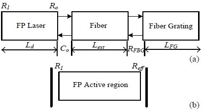 |
Fig. (1). (a) Schematic structure of FGFP laser and (b) Simplified configuration [11-14]. |
This configuration may be conveniently analyzed as a simple two-mirror laser structure (Fig. 1b) by replacing the FP diode laser output facet reflectivity Ro by a complex-valued effective reflection coefficient Reff [12-14].
 |
(1) |
where ωτe is the phase of the reflected light that travels through the external cavity and ω is the laser angular frequency. In (1), ROFB = Co Rext is the amount of optical feedback reflection that coupled into FP laser diode, where Co is the amplitude coupling coefficient between the FP laser diode and the grating fiber, and Rext is the power reflectivity of FG defined as [15, 16]
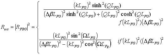 |
(2) |
where LFG is the grating length, Δβ is the wavelength detuning, k is the coupling strength,
 , and
, and
 . The phase coefficient for reflection light θref is derived from the differential equations in [15] and is given by:
 |
(3) |
By considering the phase change introduced by the optical filter in (1), Reff can be rewritten as:
 |
(4) |
After modifying the well-known expressions for the FP laser [17] by taking into account the effect of FBGs reflectivity and coupling coefficient (Co), the total cavity loss (αtot) of FGFP laser model is given by:
 |
(5) |
Where αint is the internal loss of the FP laser cavity.
3. RESULTS AND DISCUSSION
In this study, a FGFP laser with uniform FBG operating at 1550 nm wavelength is analyzed. The parameters of the laser model used in the analysis are Ld =400 μm, αint = 1000 m-1and R1 = 0.9.
Fig. (2) shows the effective reflectivity (Reff) of FGFP laser model function to the grating length coefficient (kLFG) at different values of amplitude coupling coefficient (Co). Stable fundamental lateral mode operation up to high power is required to achieve high laser-to-fiber coupling efficiency (Co), so by increasing the gratings length (kLFG) with increasing the coupling between the laser cavity and gratings fiber, the power reflectivity of FG (Rext) will be increased due to increase in the reflective strength [16] then increasing Reff; and this result seems to be consistent with what is given in Eqs. (2) and (4). In addition, result shows that for kLFG > 2.5, the Reff saturate approximately at its value with increasing Co.
Fig. (3) shows the effective reflectivity (Reff) of FGFP laser model function to the amplitude coupling coefficient (Co) at different values of grating length coefficient (kLFG) Since coupling loss occur twice during each reflection, thus the power coupling between the fiber gratins (FGs) and the active laser cavity is very important.
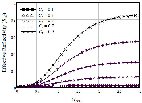 |
Fig. (2). Effective reflectivity (Reff) of FGFP laser model function to the grating length coefficient (kLFG) for different values of amplitude coupling coefficient. |
Therefore, with increasing Co, the optical coupling between the laser cavity and the FG will increase. This will reduce the output leakage from the laser cavity and also increase the incident light on the gratings fiber; and then increasing Reff. The increasing of Reff with increasing Co is smoothly linear and Reff is maximum if Co is maximum. On the other hand, for kLFG > 2.5 there is no significant impact on Reff with increasing Co.
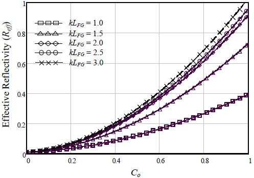 |
Fig. (3). The effective reflectivity (Reff) of FGFP laser model function to the amplitude coupling coefficient (Co) at different values of grating length coefficient (kLFG). |
Fig. (4) shows the total cavity loss (αtot) of FGFP laser model function to the grating length coefficient (kLFG) at different values of amplitude coupling coefficient (Co). As shown, αtot is relatively inversely proportional to increasing kLFG. This decreasing is due to increasing Reff as shown in Fig. (2); where with increasing the total reflectivity, the multi reflection inside the active region (as shown in Fig. 1b) will increase and this leads to reduce in the mirror loss for the cavity and then reduce αtot. This is because αtot; as is well-known it relies heavily on mirror loss (as given in Eq. 5) and not on αint [17]. Also, result shows that for kLFG 1.5, αtot is not significantly affected with increasing Co. In addition, αtot can reduce below 100/cm through operating with Co = 0.9 and kLFG ≥ 1.5.
 |
Fig. (4). Total cavity loss (αtot) of FGFP laser model function to the grating length coefficient (kLFG) at different values of amplitude coupling coefficient (Co). |
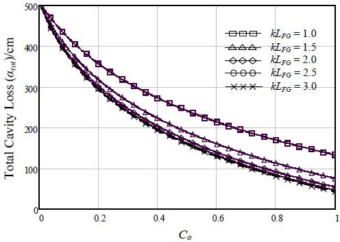 |
Fig. (5). Total cavity loss (αtot) of FGFP laser model function to the amplitude coupling coefficient (Co) for different values of grating length coefficient. |
Fig. (5) shows the total cavity loss (αtot) of FGFP laser model function to the amplitude coupling coefficient (Co) at different values of grating length coefficient (kLFG). As shown, with increasing Co; the total loss is reduced obviously. In addition, when kLFG is increased from 1 to 1.5, the reduction in the αtot with increasing Co is shown to be the maximum more than ever before. Also, result shows that the value of Co on total loss reduction is somewhat ineffective with kLFG ˃2.
 |
Fig. (6). Combine effect of amplitude coupling coefficient (Co) and grating length coefficient (kLg) on (a) Effective reflectivity (Reff) and (b) Total cavity loss (αtot) of FGFP laser model. |
Finally, the combine effect of amplitude coupling coefficient (Co) and grating length coefficient (kLFG) on effective reflectivity (Reff) and total cavity loss (αtot) of FGFP laser model is shown in Fig. (6), respectively. As can be seen, a highly effective reflectivity and very low total cavity loss can be produced by increasing kLFG and Co. As a result, increasing the kLFG and Co leads to increase effective laser reflectivity and this leads to reduce the laser cavity loss. Fig. (6) shows that the designer can control the Reffleads to increase effective laser reflectivity and this leads to reduce the laser cavity and αtot values by optimizing the kLFG and Co, values. This can reduce the total cost due to reduction in the total design complexity.
CONCLUSION
A numerical study on the effects of gratings length (kLFG) and amplitude coupling (Co) coefficients on the effective reflectivity (Reff) and the total cavity loss (αtot) of a FGFP laser is successfully conducted. It has been shown, through simulation, Reff and αtot are extremely sensitive to the kLFG and Co coefficients. It has also been shown that for kLFG ˃2, the value of Co is somewhat ineffective on total loss reduction. In addition, by optimizing the kLFG and Co, αtot can be reduced below 100/cm.
CONFLICT OF INTEREST
The author confirm that this article content has no conflict of interest.
ACKNOWLEDGEMENTS
Declared none.
REFERENCES
| [1] | Vengsarkar AM, Reed WA. Dispersion-compensating single-mode fibers: efficient designs for first- and second-order compensation. Opt Lett 1993; 18(11): 924-6. |
| [2] | Nielsen L, Knudsen S. Dispersion compensating fibers. Opt Fiber Technol 2000; 6: 164-80. |
| [3] | Agrawal G. Optical fiber communications systems. 3rd ed. John Wiley and Sons, Inc. 1997. |
| [4] | Ouellette F. Dispersion cancellation using linearly chirped Bragg grating filters in optical waveguides. Opt Lett 1987; 12(10): 847-9. |
| [5] | Williams J, Bennion I, Sugden K, Doran N. Fiber dispersion compensation using a chirped in fiber Bragg grating. Electron Lett 1994; 30: 985-7. |
| [6] | Quellette F. Fiber Bragg gratings help WDM push limits of fiber capacity. Laser Focus World 1998; 15(7): 83-9. |
| [7] | Kersay A, Davis M, Patrick H, et al. Fiber grating sensors. J Lightwave Technol 1997; 15: 1442-63. |
| [8] | Grosche E, Meissner J. Fiber Bragg gratings as wavelength references – development and characterization. In: 12th Symposium on Optical Fiber Measurements. Boulder: NIST 2002; pp. 83-6. |
| [9] | Timofeev F, Bayvel P, Mikhailov V, et al. 2.5 Gbit/s directly- modulated fiber grating laser for WDM networks. IEEE Quantum Electron Lett 1997; 33: 1406-7. |
| [10] | Ohtsubo J. Semiconductor lasers. Berlin, Heidelberg: Springer-Verlag 2008. |
| [11] | Hisham H, Abas A, Mahdiraji G, Mahdi M, Noor A. Improving the characteristics of the modulation response for fiber grating Fabry-Perot lasers by optimizing model parameters. Opt Laser Technol 2012; 44: 1698-705. |
| [12] | Hisham H, Abas A, Mahdiraji G, Mahdi M, Noor A. Characterization of the small-signal intensity modulation for single-mode fiber grating Fabry-Perot lasers. Opt Rev 2012; 19: 64-70. |
| [13] | Hisham H, Abas A, Mahdiraji G, Mahdi M, Noor A. Characterization of phase noise in a single-mode fiber grating Fabry-Perot laser. J Mod Opt 2012; 59: 393-401. |
| [14] | Hisham H, Abas A, Mahdiraji G, Mahdi M, Adikan F. Characterization of turn-on time delay in a fiber grating Fabry-Perot lasers. IEEE Photonics J 2012; 4: 1662-78. |
| [15] | Hisham H, Abas A, Mahdiraji G, Mahdi M, Noor A. Linewidth characteristics of un-cooled fiber grating Fabry-Perot laser controlled by the external optical feedback. Optik (Stuttg) 2013; 124: 1763-6. |
| [16] | Othonos A, Kalli K. Fiber bragg grating: Fundamentals and applications in telecommunications and sensing. Artech House 1999. Available from: http://photonics.ucy.ac.cy/bragg.htm |
| [17] | Agrawal G, Dutta N. Long-wavelength semiconductor lasers. New York: Van Nostrand Reinhold 1986. |


