RESEARCH ARTICLE
Experimental Simulation of the Behaviour of Diagnostic First Mirrors Fabricated of Different Metals for ITER Conditions
V.S. Voitsenya1, *, A.F. Bardamid2, A.J.H. Donné3, 4, 5
Article Information

Identifiers and Pagination:
Year: 2016Volume: 3
First Page: 23
Last Page: 54
Publisher Id: PHY-3-23
DOI: 10.2174/1874843001603010023
Article History:
Received Date: 4/7/2015Revision Received Date: 5/8/2015
Acceptance Date: 12/9/2015
Electronic publication date: 29/07/2016
Collection year: 2016
open-access license: This is an open access article licensed under the terms of the Creative Commons Attribution-Non-Commercial 4.0 International Public License (CC BY-NC 4.0) (https://creativecommons.org/licenses/by-nc/4.0/legalcode), which permits unrestricted, non-commercial use, distribution and reproduction in any medium, provided the work is properly cited.
Abstract
In the experimental fusion reactor ITER, the plasma-facing component of each optical and/or laser diagnostic needs to be based on reflective optics with at least one mirror (first mirror) facing the thermonuclear plasma. The different kinds of radiation emanating from the burning plasma (neutrons, neutral atoms, electromagnetic radiation) create hostile operating conditions for the first mirrors. Therefore, a special program has been set up under the ITER framework aimed at solving the first mirror problem. This paper will review the main results in this field that have been obtained in the Institute of Plasma Physics, National Science Center “Kharkov Institute of Physics and Technology” (in many cases in cooperation with groups of other countries, as indicated in corresponding parts of the manuscript) during long-term investigations directed to find a solution of this problem, i.e., to find a material and accompanying precautions in order to satisfy the requirements for first mirrors. The main efforts were devoted to finding solutions to overcome the impact of the most severe deteriorating factors resulting in degradation of the optical properties of mirrors: sputtering by charge exchange atoms and deposition of contaminants. The obtained results are focused on: the effects of long term sputtering on mirror specimens fabricated from different metals with different structures (polycrystals, single crystals, metal film on metal substrates, amorphous), the effects of contaminating film and the possible protection to avoid of its appearance, the role of chemical processes for some metal mirrors, and the choice of material of laser mirrors.
1. Introduction
At present, the construction of the experimental fusion reactor ITER is underway in France [1]. The first burning plasma in ITER is expected in about 10 years from now. ITER will initially be operated with hydrogen and helium as a working gas, and then gradually change in to operation with deuterium and later deuterium-tritium plasmas. During these phases the ITER device will become radio-active and from then onwards all components of diagnostic and control systems close to the plasma will be exposed to rather high neutron and gamma fluxes. To ensure reliable operation of ITER over a long time, all diagnostics need to be as robust as possible as it will be very difficult and cumbersome to reach and repair components that are deep in the port plugs and close to the plasma.
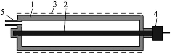
During ITER operation many different plasma and machine parameters must be diagnosed for machine protection, plasma control and also for physics evaluation [2, 3]. Approximately 40% of all plasma parameters will be measured by optical and/or laser-based diagnostics in a wide range of wavelengths (ranging from the x-ray region, the vacuum ultraviolet, visible, infrared to the millimeter wave region). Since dielectric optical components (lenses, prisms, windows, fibers) will quickly degrade due to radiation-induced absorption and/or emission, caused by the high gamma- and neutron fluxes emerging from the thermonuclear plasma [2], they cannot be applied as plasma-facing components. Therefore diagnostic designs should include one or more reflective mirrors as plasma-facing components. More or less all optical designs for ITER will include: (i) a plasma-facing mirror (the so-called first mirror, FM) which is closer to the plasma than any other component of the diagnostic, (ii) a secondary mirror (or a limited number of such mirrors), (iii) lenses or fiber-optic light guides arranged in a periscope labyrinth (but only in positions where the fluxes of neutrons and gammas are much lower, and do not deteriorate their characteristics), and (iv) the output window, as schematically shown in Fig. (1). All diagnostics components in the ITER port plug will experience to a certain degree the impact of radiation from the thermonuclear plasma, but it may be evident from Fig. (1) that the FMs will be exposed to the most hostile conditions. Along with gamma- and neutron radiation, they will be exposed to: (i) electromagnetic radiation ranging from soft X-rays up to millimeter wave radiation, and (ii) the flux of charge exchange atoms (CXA) having a wide energy spectrum (average energy being a few hundreds of eV [4]) and a flux density being approximately the same as that of the CXA flux to the first wall of the reactor.
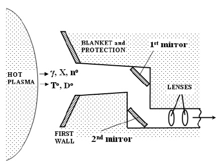 |
Fig. (1). Schematic layout of optical measurement components. |
Electromagnetic radiation can heat and deform the mirror, which can be largely remedied by active mirror cooling. More difficult to cope with are the effects of neutrons and of the CXA flux on the mirrors. Neutrons, but in particular CXA will cause changes in the optical properties of the mirrors and in general a degradation of the optical properties (neutrons lead to the formation of various defects in the mirror material, while the CXA flux causes surface sputtering and roughening). The combined effect of these two factors may give rise to synergistic effects, which should be addressed in experiments simulating the mirror performance in ITER, to ensure that the mirrors foreseen for ITER survive the hostile environment for a long enough time. Taking into account the flux (~ 2·1015 at/cm2 s) and mean energy (a few hundred eV) of CXA from [4], and the sputtering yield data from [5], one can estimate the depth of the sputtered layer for various materials during the full service time of the ITER reactor for D-D and D-T operational phases, i.e. about 10,000 working pulses with duration 400 s. The depth of the layer sputtered under these conditions is a few μm for tungsten, more than ten μm for molybdenum, and several tens of μm for rhodium and copper. In the case of a polycrystalline metal structure, the sputtering will result into the development of surface roughness and, as a result, a degradation of the mirror optical properties.
Another contribution to the degradation of optical properties of any in-vessel mirrors in ITER will be due to deposition of contaminants (that have been sputtered from components elsewhere). In the original ITER design the divertor tiles, that will experience the highest particle and heat loads, were supposed to be made of carbon-carbon composites. Under these conditions carbon would be the main component of any layer that could be deposited on the first mirrors. Therefore, many efforts were made to develop methods to clean mirrors from a carbonized deposit. However, the present ITER design features a W divertor and Be tiles in the main plasma chamber. Hence, these elements will be the main constituents of any deposited layer with additionally and unavoidably oxygen, and probably to a much lower degree, carbon. This paper will therefore focus on especially these materials.
This paper will review and discuss the main results achieved at IPP NSC KIPT:
- Simulation studies into the behaviour of mirrors exposed to long-term sputtering by deuterium plasma ions; featuring mirrors being made from different bulk metals with polycrystalline structure, single-crystal structure, metal films on metal substrate, and mirrors made from metal amorphous alloys;
- Experiments mimicking the simultaneous impact of neutron radiation and charge-exchange atoms on metal mirrors;
- Studies of the influence of repetitive laser pulses on the optical properties of the first-mirror of the ITER Thomson scattering system;
- Chemical processes on metal surfaces exposed to a hydrogen (deuterium) plasma contaminated with C or O.
In the paper only information is given about the sputtering procedures. In all cases where the sputtering conditions are not indicated, ions were used from a deuterium plasma (with electron temperature and density Te≈5 eV and ne≈1016 m-3, respectively) produced by an electron cyclotron resonance source (frequency 2.45 GHz) in the double-mirror magnetic configuration of the DSM-2 stand [6].
The deuterium ions are accelerated to the substrate surface by applying either a fixed or a time-variable negative voltage with ion current ~10 A/m2; in the latter case a wide energy distribution of projectiles can be realized (in the range 50-1350 eV), qualitatively mimicking the energy distribution of charge exchange atoms in fusion devices, e.g. ITER. References to the detailed description of the experimental conditions used for the various experiments will be given in the text.
2. Effect of a plasma on the performance of different types of mirrors
2.1. Polycrystalline Mirrors
2.1.1. Mirrors for the Near UV and Visible Region
Experiments with mirrors made of polycrystalline (PC) metals: Be, Al, Cu, Ti, Mo, W, Ta, and stainless steel (SS) have demonstrated that none of them will keep their initial reflective properties under long-time sputtering. During sputtering of the PC mirror surface, gradually a relief develops, which is due to the fact that differently oriented grains in the metal are sputtered at different rates. In this way a stepped surface structure arises [6, 7], with different plateaus that relate to the different crystal face orientations.
This can be easily seen in Fig. (2) obtained by the electron backscatter diffraction (EBSD) technique, which shows the face orientations of all individual grains seen on the surface of a polycrystalline SS mirror [8]. Some grains even exhibit the development of a smaller-scale relief (Fig. 2). The probability of this to occur depends on the grain orientation, as described, for example, in ref [8]. In the case of stainless steel (SS), the densest face (111) appears to be the most resistant in this respect, even though it has the highest sputtering rate.
Similar experiments were performed with PC tungsten mirrors [10]. The experimental data are in qualitative agreement with the results obtained for SS mirrors. However, stainless steel and tungsten belong, respectively, to fcc and bcc metals. Therefore, it is understandable that in tungsten, contrary to SS, it is the (111) face that is the most sputtering resistant (Fig. 3), while the grains with (110) orientation (most dense) at the surface have the highest sputtering rate.
It is also evident from combined profilometry and EBSD data (see Fig. 3b) that a small deviation (~9°) from the exact orientation of the (111) face lying on the surface did not change much of its sputtering rate compared to the others. This fact was used as a qualitative basis for modeling of the relief that develops on the polycrystalline mirror under sputtering [11], (see below). It may be evident that a “stepped” surface relief results in degradation of the optical properties of the mirror.
 |
Fig. (2). SS mirror surface relief after exposure to hydrogen ions (energy 1.5 keV, fluence 1.1·1021 m-2; sputtering was done at the University of Toronto Institute for Aerospace Studies, Toronto, Canada [9]). The marks at the grains indicate their crystal orientation. |
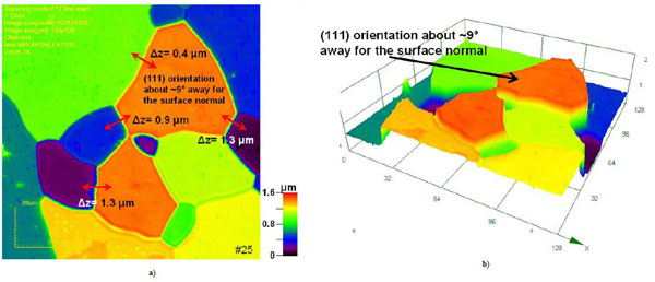 |
Fig. (3). Two- and three-dimensional surface images ((a) and (b), respectively) of laser profilometry data for PC tungsten mirror after 4 μm sputtering (averaged, found from weight loss measurements) by 600 eV ions of argon plasma [10]. In (b) the result of EBSD measurements for the highest grains are shown. |
The surface roughness, and consequently, the degradation rate of the specular mirror reflectivity at normal incidence (R) increases with increasing energy of the ions that sputter the mirror surface, as was first established in refs. [6, 7]. Fig. (4a) shows the behavior of R of SS mirrors at a wavelength of 600 nm, versus the depth of the layer sputtered by hydrogen plasma ions of different energies. The depth was determined from the sample weight loss. Fig. (4b) is derived from Fig. (4a) and shows the reflectance versus ion energy for a 4 μm thick eroded layer. Increasing the ion energy leads to a faster enhancement of the surface roughness and, correspondingly, to a faster degradation of mirror optical properties. This effect is attributed to the fact that the difference between the sputtering rates of metal grains with different orientations increases as the energy of the bombarding ions increases. This topic was not addressed before in literature.
 |
Fig. (4). Reflectivity degradation of SS mirrors exposed to hydrogen plasma ions of different energies [7]. The average energy for ions having a wide energy distribution (470 eV) has been determined with due account for simultaneous presence of H+, H2+ and H3+ ions in the hydrogen plasma. |
The authors of ref [11] have analysed the results of long-duration sputtering experiments on polycrystalline metal mirrors with crystal grains of different sizes ranging from tens of nanometers to tens of micrometers. Included in their study were: (i) mirrors produced through annealing of amorphous alloys (crystallite size 30 to 70 nm); (ii) thin film mirrors (Rh film on a Cu substrate, crystallite size being ~100 nm); (iii) fine-grained Cu, Mo and W mirrors (grain size 250-350 nm); (iv) ITER-grade tungsten mirrors with strong anisotropy of grains (grain size being 1–3 μm and ~5 μm along the surface and perpendicular to it, respectively), and (v) tungsten mirrors that were recrystallized at 2073 K after high-quality polishing (grain size between 10 and 100 μm [10]). The relief data obtained with the use of an atomic force microscope (AFM) or a laser profilometer were analysed in detail, and based on that, a model for the roughness development on PC mirrors during sputtering has been developed; its detailed description can be found in ref [11].
The model relies on the fact that in a polycrystalline metal the sputtering coefficient of every separate grain depends on the orientation of its crystallographic axis in relation to the surface. It is reasonable to assume that an insignificant deviation from the exact orientation of the crystallographic axes, e.g., within ±15°, causes no appreciable changes in the sputtering coefficient, as was seen in the analysis of W mirror samples with EBSD (see Fig. 3b).
The basic idea encompassed in the model is the following:
If no special measures are taken to texturize the metal (e.g. as the ones employed in single crystal growing), then during cooling of the molten metal in the manufacturing process, the probability direction of its grain orientation is uniform over the range 0° - 360°. So, there will be a great probability that some grains, which are close to one of the crystal orientations, will form somewhere on the surface a more or less isolated group with approximately the same sputtering coefficient, while other grains with another orientation will be grouped at a certain distance along the surface and will have a noticeably different sputtering coefficient. Thus, the relief that will develop on the surface will be characterized in its longitudinal length not only by the size of the separate grains, but also by the sizes of the mentioned groups and by the distance between them.
The appearance of groups with close grain orientations inside the group, but with different orientations between the groups, is well illustrated by Fig. (5a), which was obtained by EBSD when analyzing a sample of a recrystallized tungsten surface. As can be seen from the comparison with the stereographic triangle that indicates the orientation of individual grains, there are many grain groups that are a little different in color, i.e. they have only a small difference in the sputtering rate.
The model has been used in the treatment of the surface relief data obtained with an Atomic Force Microscope (AFM) for the above-mentioned mirror samples (except for the amorphous crystalline sample, where the surface was examined using a scanning microscope, and the recrystallized tungsten sample examined with a laser profilometer). Longitudinal inhomogeneity distribution functions of the surface roughness (along the processed trajectory on the surface) have been obtained. Fig. (5b) shows the distribution of longitudinal wavelengths as a function of the wavelength for the recrystallized W mirror sample, shown also in Figs. (5 and 3b).
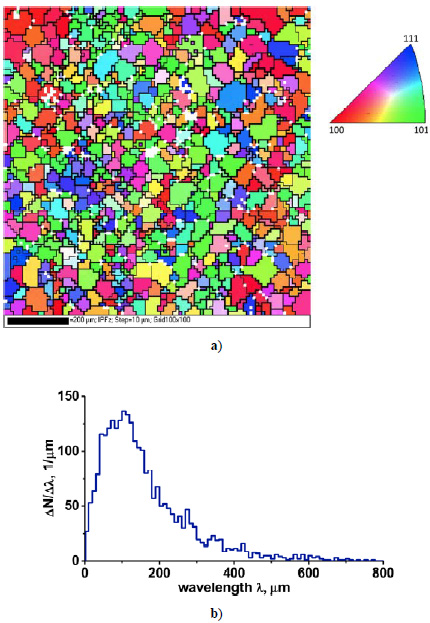 |
Fig. (5). (a) EBSD data obtained for a PC tungsten mirror after its sputtering to ~ 4 µm deep; (b) processed laser profilometry data: size distribution of relief inhomogeneities along the same W sample surface [11]. |
As can be seen, the spectrum displays inhomogeneities along the surface length with a size that is equal to or much larger than the typical size of the majority of the grains (10 – 100 μm) observed in tungsten of this type. The same effect is also (qualitatively) observed for similar distributions obtained on the relief data treatment for other mirror samples mentioned above.
The random scatter of conventional “crystals” on the plane has been simulated [11], with a model assuming crystals having one size (1 μm x 1 μm) or two sizes: (1 μm x 1 μm) and (2 μm x 2 μm); (1 μm x 1 μm) and (3 μm x 3 μm); (1 μm x 1 μm) and (4 μm x 4 μm). Each set of “crystals” had its spatial orientation ranging from 0° to 360°, with different “sputtering coefficients” ranging from 0 to 0.5 for different (six) orientations, though being fixed for each orientation within the ±15° deviation from the true orientation. For variants of two-size “crystals”, the total area of the “crystals” of both types was the same. The “relief” characteristics for each of the four variants were found by the procedure described in ref [11]. The scatter simulation procedure was repeated six times for each of the variants, upon which averaged results were determined (see Fig. 6).
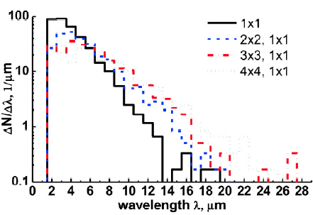 |
Fig. (6). Distribution of longitudinal “relief” inhomogeneities at simulation of sputtering of randomly spread “crystals” of sizes indicated in the legend [11]. |
It follows from the figure that in all cases the “relief” has components, with longitudinal sizes that by far exceed the sizes of the largest crystal grains. If we consider the probabilities of their appearance (ΔN/Δλ) only within one order of magnitude from the maximum, then the inhomogeneity size changes from 8 μm to 14 μm, respectively, starting from the one-dimensional variant (1x1) to the variant with the presence of the largest crystal grains (4x4).
So, the experimental results as well as the simulation data testify that even with the use of polycrystalline metal mirrors with crystal sizes much smaller than the reflected emission wavelength, the relief appearing under sputtering will lead to degradation of the reflectivity. An illustrative example is furnished by the appearance of a relief with a characteristic inhomogeneity size of ~1 μm on the surface of a mirror made from a crystallized amorphous alloy, in which the crystal grain size varies between 30 and 70 nm [11].
2.1.2. Retroreflectors for the Infrared Region
The results presented above do concern the consequences of sputtering of polycrystalline mirrors on the reflectivity in the near UV and visible spectral range. However, as follows from the obtained data (e.g., Fig. 5b), similar effects can occur for the reflectance at much longer wavelengths, i.e. for the infrared spectral range (IR) ~10 μm which is planned to be used in ITER for toroidal interferometry/polarimetry [12]. The measurement scheme will include corner-cube retroreflectors (CCR), implying that the light is reflected by three surfaces before returning in the original direction. Due to this triple reflectance the effect of any surface roughness can significantly deteriorate the intensity of the signal returning to the receiver. The CCRs will also be used in the poloidal polarimeter/interferometer system of ITER operating at 118.8 μm [13], so some roughness effects for this case can be possible as well.
To understand the effects of CXA sputtering on the operating characteristics of CCRs a special study was performed to simulate the impact of the ITER environment on retro-reflectors for both infrared wavelengths [14]. In the simulation experiments the CCR was modeled by a “model retroreflector” composed of three separate polycrystalline mirrors. As mirror material polycrystalline oxygen-free copper with a rather small dimension of grains (<100 µm in size) and a polycrystalline CuCr alloy (dispersion-strengthened copper alloy) with a total content of ~1% Cr addition were used. Copper was chosen to reduce the time of the experiment because of its much higher sputtering rate in comparison to molybdenum and tungsten, which are the most promising materials for CCRs in ITER. A comparison was made of the reflectance of an unsputtered CCR model with ideal mirrors, and the reflectance of the same CCR model after every individual mirror surface was sputtered to a depth of ~5 μm by ions of deuterium plasma with a wide energy distribution. This depth value was estimated to be close to the one for Mo CCR under impact of CXA in ITER during the full operational life time. The re-deposition of eroded material inside the CCR described in [15] was not taken into account in this study. In addition to the reflectance, also the rotation of the polarization angle upon reflection by the CCR was measured before and after the sputtering procedure.
More details of the experiments can be found in [14]. Here we present only the main results in Tables 1 and 2 for the reflectance of three copper mirrors in series at λ=118.8 μm and λ=10.6 μm, correspondingly, before and after a layer of ~5 μm thickness was eroded. The single reflection data were calculated from the triple reflection measurements.
Effect of sputtering on “CCR” at λ=118.8 µm.
| Mirror Samples | R Before Ion Bombardment | R after Ion Bombardment | ||
|---|---|---|---|---|
| Single Mirror | “Retro-Reflector” | Single Mirror | “Retro-Reflector” | |
| O-free copper | 97.7% | 93.5% | 97.8% | 93.7% |
| CuCr | 99.2% | 97.6% | 97% | 91% |
Effect of sputtering on “CCR” at λ=10.6 µm.
| Mirror Samples | R before Ion Bombardment | R after Ion Bombardment | ||
|---|---|---|---|---|
| Single Mirror | “Retro-Reflector” | Single Mirror | “Retro-Reflector” | |
| O-free copper | 97% | 91% | 87% | 66% |
| CuCr | 96% | 90% | 42% | 7.3% |
As evident from the data in [14], sputter erosion of a 5 µm deep layer would not result in a noticeable decrease of the CCR reflectance at λ = 118.8 μm. However, a similar rate of erosion is practically inadmissible for the CCR system operating at λ = 10.6 μm. To solve this difficulty: (i) the CXA flux to the CCR surfaces has to be significantly decreased by putting the CCR in a proper location and to protect it as much as possible from the nearby environmental conditions, or (ii) the CCR has to be fabricated from tungsten having a much lower sputtering rate than molybdenum, or (iii) each CCR mirror has to be fabricated from molybdenum with a single crystal structure.
One more important result found in these studies is a strong impact of the mirror roughness on the polarization of the reflected beam for λ=10.6 μm: after reflection from all three sputter-eroded mirrors the polarization angle changed by ~9°C. This sputtering effect on the operational properties of the retroreflector can be significantly decreased by the use of tungsten as material for the CCR surfaces. An even better result, with probably full suppression of the surface roughening can be achieved if the CCR surfaces are made from monocrystalline molybdenum or tungsten (see next section),
A strong effect on the polarization of the reflected beam of light was shown to occur also due to a deposit of a contaminating layer on top of the mirror. This was shown experimentally for a C film [3] and theoretically for Be and C films [16]. Because of the high impact this effect can have on the operation of the ITER polarimetry diagnostics, a special study is required in which the mirror properties are studied in conditions with a deposited contaminant layer composed by the first wall materials to be used in ITER (Be and W).
2.2. Single-crystalline Mirrors
Understanding the reason of polycrystalline mirror degradation gives a clear hint that the step structure development can be possibly eliminated by applying mirrors from single crystals (SC). Experiments were performed with SC mirrors made from molybdenum, tungsten, nickel, and stainless steel with different orientations of the basic crystallographic axes (100), (111), (110). The samples were sputtered by deuterium plasma ions having a wide energy distribution. The behavior of SC mirrors was investigated in the course of long-term sputtering [3, 17, 18], during which the mirrors showed a considerably higher resistance to relief development under erosion than the polycrystalline mirrors did (Fig. 7). This result was corroborated by co-operative experiments at the large operating fusion facilities Tore Supra (France) [19] and TEXTOR (Germany) [20].
Based on these data, the ITER community has made the decision that SC molybdenum should be the first mirror material for plasma diagnostics in ITER. This material has a rather low sputtering coefficient and a moderate reflection coefficient R in the near ultraviolet and in the visible-light spectrum.
The above mentioned results indicate that the solution of the first mirror problem could rely only on the choice of those materials which exhibit a homogeneous surface erosion during long-term sputtering. As was mentioned above, such materials are metals that have a low sputtering rate (W, Mo) and a single-crystal structure.
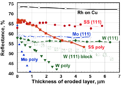 |
Fig. (7). Comparison between the reflectances as function of the eroded layer thickness, for mirrors made from different PC and SC metals, and also, for a film mirror with a Rh film on a Cu substrate. The symbol “W (111) block” shows the data obtained at sputtering of PC textured tungsten with the (111) orientation of the majority (≈96%) of all grains [3, 18]. |
However, under ITER conditions there is a high probability that under impact of γ- and neutron radiation the single crystal will loose its perfect crystallographic structure, and then, the sputtering by charge exchange atoms may result in the development of surface roughness and the subsequent loss of optical properties. This was confirmed by experimental data on sputtering of SC Mo mirrors that have a defected structure, which showed a substantial degradation of the reflectance versus the sputtered layer thickness, though still at a lower rate in comparison to the degradation of PC Mo mirrors [3, 21]. To our knowledge, no experiments on single-crystal mirror surfaces have been performed in which the impacts of gamma and neutron radiation, and of ion bombardment are combined.
2.3. Film Mirrors
The production of single crystal mirrors with the required dimensions for ITER (≥10 cm) is not an easy task. Therefore, consideration has been given to another possibility of avoiding the appearance of the step structure at polycrystalline mirror sputtering, namely, through coating of the mirror surface with a metal film that has a rather high R (Rh, Mo) and thick enough (a few μm) to withstand the long-term sputtering by charge exchange atoms at the mirror location in the ITER port plug. Generally, such films have a fine-crystalline structure (≤100 nm). Therefore, it was expected [22] that the scale of microrelief, which appears after long-term sputtering may be appreciably shorter than the light wavelength range for which the mirror is applied.
Experiments with different films on various substrates (Be/Cu, Cu/Cu, Rh/Cu, Rh/V, Rh/SS, Mo/SS, Mo/Mo) have shown large differences in their behavior on exposure to deuterium plasma ions. If the film adhesion to the substrate is strong, the optical properties of these mirrors were almost not affected by long-term sputtering. For example, some Rh/Cu specimens prepared by pressing the films onto the Cu substrates, retained their properties even after sputtering of a layer of more than 7 μm thick (see Fig. 7) [3, 17]. Unfortunately, that technology cannot be applied (yet) for producing such thick film mirrors (thickness (10 μm) with an area large enough (~10 cm in diameter) to be of interest for application in ITER.
At present, at least three groups are investigating the prospect to use metal film mirrors for ITER plasma diagnostics: the University of Basel (Switzerland), the Politecnico di Milano (Italy), and the Indian Institute of Technology Guwahati (India). The Basel group operates with Rh films (and to some extent also Mo films) produced by magnetron sputtering and has a typical thickness ~2 μm (e.g., [23]). The two other groups study the behavior of films obtained by a pulsed laser deposition technique in vacuum [24, 25]. All main publications connected with investigation of film mirrors were recently enumerated in a short review [26].
Film mirrors were tested in small laboratory set-ups [27-29] and in large fusion devices TEXTOR [23], DIII-D [30], JET [31, 32]. Thanks to the improving technology there are prospects for such mirrors to be used in ITER. Note that because of the small film thickness and the rather high sputtering rate (for Rh film) the important condition for their use as first mirrors is to achieve a significant attenuation of the CXA flux density to the mirror surface, e.g., by strongly limiting the size of the input pupil. This was suggested for the ITER Hα monitor [33] and recently realized in experiments at T-10 [34] and JET [26] in which large size (200x300 mm) Rh film mirrors were employed.
Since the metal films are generally polycrystalline in their structure, at long-term sputtering their surface will gradually become rough with the result that the optical properties slowly degrade. This effect does strongly depend on the technology used for the film deposition. Some examples of this behavior, descibed in ref [35], were used in the analysis [11] of the experimental data obtained with polycrystalline mirrors. More details on the topic will be given below.
2.4. Mirrors from Amorphous Alloys
Mirrors made from amorphous metal alloys (AMA) may be another alternative to SC mirrors. Unlike the perfect structure of single crystals, the AMA have no structured order over a distance of several nanometers. Therefore the initial quality of their surface should remain the same, irrespective of the sputtering time. This assumption made as early as in ref [22], could be corroborated only after development of the technology for producing amorphous castings of sizes sufficient for preparing amorphous mirror samples (≥10 mm).
The experiments on mirrors made from zirconium- and titanium-based amorphous alloys have demonstrated their extra-high resistance to long-term sputtering [36, 37]: the amorphous mirror with composition Zr(41.2)Ti(13.8) Cu(12.5)Ni(10)Be(22.5) has kept its optical properties even after sputtering of a 13.4 μm thick layer (Fig. 8). The microscopic examination of the mirror surface has revealed no changes in comparison to the initial value before sputtering.
 |
Fig. (8). Amorphous mirror reflectance at the given wavelengths versus the layer thickness sputtered for many exposures by ions of argon plasma with different fixed energies, ranging from 0.1 to 1.35 keV [36]. |
Although this sounds promising, AMA mirrors have the disadvantage that they absorb hydrogenic ions at a rather high rate. Certainly when operating ITER with tritium this would lead to a high tritium retention. Experiments on the interaction of a deuterium plasma ions of a few tens of eV with amorphous ZrTiNiCuBe mirrors were performed to study this effect [37]. Deuterium retention in these conditions is much more efficient than in experiments where hydrogen saturation was studied by exposing the AMA mirror to the gas phase or electrolytic solution. From the measured dependence of the absorbed deuterium mass on the ion fluence (up to 1.5·1025 ion/m2) it was possible to estimate the efficiency of deuterium absorption to be ~10% for an ion energy of ~60 eV. This is about ten times higher than in the electrolytic hydrogenation experiments [38]. This is attributed to the fact that the hydrogen (deuterium) plasma ions of these energies can easily penetrate to a depth greater than the oxide layer thickness (a few nm), and can immediately get into the bulk of the material, whereas in the case of gas-phase hydrogenation, for example, the absorption process goes through several stages, viz., physical molecular absorption, molecular dissociation, chemical desorption, and only then inward diffusion follows [39].
The high absorptive capacity in relation to hydrogen isotopes holds no promise for the ZrTiNiCuBe amorphous alloys to be used as a material for the plasma facing mirrors in ITER. However, the rather rapid progress in the development of amorphous materials gives hope that in the future AMA mirrors with a low absorptive capacity (for hydrogen and its isotopes) will be designed, which would permit their use as a material for in-vessel mirrors under conditions of high fluxes of charge exchange atoms, neutrons and gamma-radiation.
3. Influence of chemical processes on optical properties
3.1. Beryllium Mirrors
Beryllium has been chosen as the first wall material of ITER, because of its low atomic number (Z=4) on the one hand in combination with the not too high a sputtering rate of Be under ITER conditions [1]. The choice of Be ensures a much lower contamination of the ITER plasma in comparison to any other metal wall, which need not necessarily be the case in future devices like DEMO. When the reactor is in operation, owing to erosion resulting from the plasma action, beryllium will propagate throughout the chamber, depositing at the sites most distant from the plasma confinement volume, including on the mirrors of optical and laser plasma diagnostics. In other words, there is a high probability that any metal mirror would become gradually covered with a beryllium film, and thus would change its optical properties. At the same time, in case of a Be mirror, the deposition of Be film on top is not expected to change much the optical characteristics of the mirror.
The basis for this assumption are data on the optical properties of beryllium that were analyzed in the paper “Beryllium” published in the Handbook of Optical Constants of Solids II, edited by Palik [40]. The majority of reflectivity data presented there were obtained with Be film deposited in vacuum. In the near UV and visible spectral range the film reflectance was noticeably higher than that of polished bulk beryllium mirror specimens.
It should be mentioned here that large differences have been observed between the optical characteristics of Be film deposited in a high vacuum [40] and in experiments with deuterium pressures of 0.5–0.8 Pa in “the PISCES-B divertor-plasma simulator” [41]. Analyzing the application of their results to ITER conditions, the authors of [41] wrote in the last conclusive remark that “…the lower pressure expected in the main chamber may lead to the formation of more dense layers, whose reflectivity is expected to be closer to the theoretical value of beryllium.”
In a detailed study on the behavior of Be mirrors exposed to deuterium plasma ions [42, 43] it was found that their optical properties strongly depend on the ion energy: with keV energy-range ions a significant drop of reflectance occurs already at relatively low ion fluence (≥5·1021 ion/m2). After the drop, the reflectance can be fully restored during a much longer time (ion fluence ≥1·1024 ion/m2) by exposing the mirror to low energy ions (~50 eV) of the same plasma. For some Be mirror specimens similar procedures (drop and restoration of reflectance) were repeated several times without decrease of the level of reflectance restoration.
Fig. (9) illustrates the repetition of the process of reflectance decrease as a Be mirror was exposed for a short time to deuterium plasma ions of keV energy, and also, the reflectance recovery during a substantially longer time, when the ion energy is low (about 50 eV). Such reflectance behavior unambiguously indicates that all variations in the optical properties are determined by the chemical processes on the Be mirror surface, and the mirror surface roughness is likely to remain at the initial level.
The given data have provided the explanation of the behavior of Be mirrors, observed on their exposure to deuterium plasma ions of different energies. Each short-term action of keV D+ plasma ions under conditions of the experimental test bench DSM-2 (with some amount of water vapor) resulted in a gradual increase in the oxidized layer thickness. This process mainly proceeds through the formation of the hydroxide Be(OD)2 by the reaction: 2BeO + 2D → Be(OD)2 + Be. The first stage of this process is characterized by a complete transformation of the existing oxide film (extinction coefficient k ≈ 0) into a hydroxide film (here k > 0 [43]) that leads to the reflectance drop after exposure to a very low ion fluence of keV energy range, to a level of ≥5x10²¹ m-2. The second stage is characterized by a relatively slower increase in the thickness of the oxide-hydroxide (possibly, only hydroxide) layer due to the reactions of free Be atoms either with new oxygen molecules to produce oxide, or with water molecules to produce hydroxide. This stage is accompanied by a gradual saturation of the reflectance drop at ion fluences of ≈2·1023 m-2 [43].
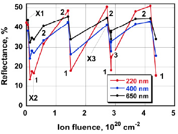 |
Fig. (9). Be mirror reflectance at the indicated wavelengths. 1 – reflectance drop due to 1350 eV ion bombardment; 2- reflectance recovery after long-term exposures to 60 eV ions; 3 – partial reflectance recovery after vacuum annealing for 2 hours at 200°C [43]. X1, X2, and X3 indicate the states of experiment when XPS measurements were provided (see Fig. 10). |
 |
Fig. (10). XPS data for the Be mirror exposed to deuterium plasma ions: ♦ – Ar+ion cleaning, Ei = 300 eV (X1 in Fig. 9); ● – reflectance drop after D+ ion bombardment, Ei= 1350 eV (X2 in Fig. 9); ■ – reflectance recovery after exposure to D+ions, Ei=60 eV, after the second reflectance drop (X3 in Fig. 9) [43]. |
As chemical analysis of the Be-mirror near-surface layer has shown (by the use of X-ray photoelectron spectroscopy, XPS), it is just this process that has been observed in our experiments with Be mirrors exposed to deuterium plasma contaminated with oxygen: after exposure of the Be sample to keV deuterium plasma ions, the oxidized surface layer became substantially thicker than the original layer (Fig. 10). At the same time, a long-term bombardment by low-energy D+ ions (Ei= 60 eV) leads to practically full recovery of both the near-surface layer thickness and the reflectance (Fig. 9), probably due to elimination of the thick oxide layer (see the discussion below).
An important feature of the second phase of the oxide-hydroxide layer thickness increase is the rate of free Be atom supply to the surface of the layer, because neither the oxygen molecules nor the water molecules can pass through this layer. The Be atom supply can be provided due to sputtering of the beryllium surface by deuterium ions that have passed through the oxide film: the higher the D+ ion energy, the higher the sputtering rate of the metallic beryllium and the higher the rate of oxide-hydroxide film thickness increase, i.e., the greater the reflectance drop [42, 43], Fig. (11). The saturation of the reflectance drop is determined by the fact that for each ion energy there exists a maximum path length in the oxygen-containing film.
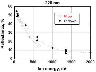 |
Fig. (11). Reflectances of two Be mirrors at λ=220 nm as function of ion energy in the phase of reflectance degradation (black rhombs) from the initial (or partially recovered) state, and in the phase of recovery (red circles) after the degradation due to exposure to higher-energy ions [43]. |
To support the process described in this paragraph we can refer to ref [44], where the rate of the oxide layer thickness growth on the Be surface was one order magnitude higher when it was bombarded by 5 keV He+ ions than in the case of 2.5 keV D+ ions, due to probably a significant difference in Be sputtering yields for these projectiles.
If in the process of exposure, the ion energy gets reduced to a value where the ion path length becomes shorter than the oxide-hydroxide film thickness, the “source” of free Be atoms (i.e., the sputtering of metal bulk) will be terminated, and another process may start. This process has the opposite effect compared to the one which has led to the increase in the oxide-hydroxide film thickness, namely, the decrease in the oxidized layer thickness and the recovery of metallic beryllium occurs by the reaction BeO + 2D → D2O + Be or Be(OD)2 + 2D→2D2O + Be. In Fig. (11), this “inverse” process is shown by red open circles. The rate of metallic beryllium recovery, i.e., the reflectance return to its initial level, goes at a considerably lower rate than the reflectance degradation, cf. the data shown in Fig. (9).
An important result obtained in Be mirror experiments is that two pc Be mirrors could withstand many procedures of reflectance drop and partial or full recovery (see Fig. 11) at the total ion fluence of 2.5x1025 ions/m2 with an average ion current density of 15 A/m2 (the total time of exposure to the deuterium plasma exceeded 60 hours). By that time both Be samples still had a mirror-like surface and retained their high ability to transmit an image of a subject (the laser beam spot) practically with similar quality as an aluminum etalon did, refs [43, 45].
The results in this section proof that the reflectance variations are not connected to the development of Be surface microrelief, but are fully due to the chemical processes in the oxide film.
3.2. Aluminum Mirrors
Qualitatively, the same effect as in Be mirrors was observed in exposure of Al mirrors to similar conditions. This is attributed to the fact that Be and Al are neighbors in the periodic table, and therefore there exists the so-called diagonal analogy, i.e., similarity in many chemical and physical properties. Our experiments have first established a close analogy in the behavior of Be and Al mirrors, as they are exposed to hydrogen plasma. This is apparent from the comparison between the data presented in Figs. (9) [43] and Fig. (12) [46].
The Al mirror experiments have provided additional insight into the processes decribed above for the Be mirrors. Secondary ion mass spectrometry (SIMS) and Auger spectroscopy techniques were used to perform layer-by-layer analysis of the near-surface layer of Al mirror samples after different operational procedures with exposure to deuterium plasma ions [46]. It has been found that a short-term bombardment by 1350 eV ions leads to an increase in the thickness of the oxygen-containing layer, while a longer exposure to low-energy ions of the same plasma causes an appreciable decrease in the layer thickness.
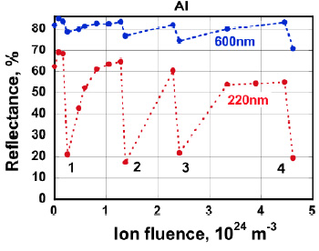 |
Fig. (12). Reflectance of an Al mirror sample at the indicated wavelengths versus the total ion fluence. Sharp falls are the result of short-term bombardment by 1350 eV deuterium plasma ions (stages 1, 2, 4) and with a wide energy distribution (100-1350 eV, stage 3). All rises are due to long-term exposures to low-energy ions (60 eV) [46]. |
This is testified, in particular, by an increased yield of AlO- and AlOD+ ions (presumably, fragments of the molecules Al2O3 and Al(OD)3, respectively) from the near-surface layer after a short-term exposure to 1350 eV ions, and by a substantial decrease in the yield of these fragments after a further long-time exposure of the samples to 60 eV ions, as the data of Fig. (13) demonstrate.
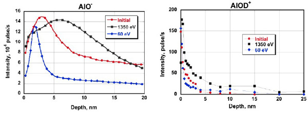 |
Fig. (13). SIMS analytic data on the composition of the near-surface layer of Al mirrors. The yields of AlO- and AlOD+ ions are given as functions of the depth of their occurrence [46]. |
The given depth distributions are very similar to the data for the ions of mass 2. These may be both the atomic ions D+ and molecular ions H2+. However, since deuterium is the operating gas, it can be stated with high probability that a great part of biatomic ion current is related to deuterium ions (Fig. 8 in ref [46]). So, actually, these data qualitatively repeat the data obtained for the fragments of Al2O3 and Al(OD)3 molecules.
The most demonstrative data have been obtained from the measurements of Al3+ cluster yields from the same aluminium samples (Fig. 14). These clusters are easily formed during sputtering of a clean metal surface. However, if the surface is coated with an oxide film, the probability of cluster formation sharply decreases, while the yield of oxygen-containing fragments increases. In our experiments, after a short-term exposure to 1350 eV ions, the thickness of the layer, which showed a gradual increase in the ion cluster yield, considerably increased. However, after a long-term exposure to 60 eV ions, the transition layer became very thin again.
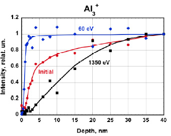 |
Fig. (14). SIMS data on the Al3+ cluster yield from the Al surface [43]. |
The SIMS data were confirmed by Auger spectroscopy as shown in Fig. (15). As can be seen, the oxide film thickness increases after bombardment by 1350 eV deuterium plasma ions, and substantially decreases after exposure to low-energy ions.
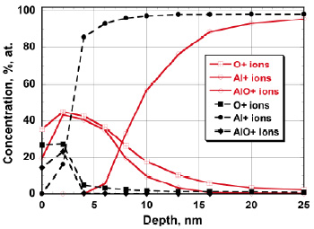 |
Fig. (15). Auger analysis data for Al mirror samples similar to those shown in Figs. (12-14). The solid lines (with open symbols) show the concentrations of the indicated components of the uppermost surface layer material as function of depth after exposure to deuterium plasma ions with energy 1350 eV, and the dashed lines (with closed symbols) show the same, but after a long time exposure to 60 eV ions. Initial data, after cleaning with Ar ions, are not shown for simplicity [46]. |
3.3. Mirrors from Amorphous Metal Alloys
This section presents a more detailed description of the behavior of amorphous mirrors versus the conditions of their exposure to a deuterium plasma, using mainly the data of ref [37] as basis.
Studies were made in mirror samples of two types, containing the same components but with different atomic ratios: type 1 - from the Zr(41.2)Ti(13.8)Cu(12.5)Ni(10) Be(22.5) alloy manufactured at the NSC KIPT, and type 2 - from the Zr(46.75)Ti(8.25)Cu(7.5)Ni(10)Be(27.5) alloy developed at the Hahn-Meitner Institute (Berlin, Germany). Both alloys contained beryllium; therefore, their behavior could be expected to be similar to that shown by Be and Al mirrors. The performed measurements have confirmed this assumption.
The exposure of the mirrors to deuterium plasma ions of high and low energies has led to similar results as those obtained in the cases of Be and Al mirrors. This similarity, at least, qualitative, can be exemplified by the data given in Fig. (16) for the samples made from the Zr(41.2)Ti(13.8)Cu (12.5)Ni(10)Be(22.5) alloy. However, unlike the Be mirrors, the reflectance changes as a function of ion energy are considerably smaller; this probably is due to the relatively moderate content of beryllium in this alloy.
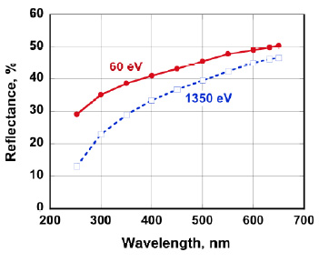 |
Fig. (16). The reflectance of an amorphous mirror specimen after exposure to 60 eV (solid circles) and 1.35 keV (open squares) ions from deuterium plasma. For this particular specimen the drop of reflectance was repeated three times and restoration after long-term exposure to low energy ions from the same deuterium plasma was repeated twice. In the figure the results after the last two procedures are shown. |
Additional important information about the effect of the ion energy on the special features of deuterium plasma interaction with amorphous mirror surfaces has been collected with the SIMS method. In order to “sponge the memory” of previous exposures, all the samples before their exposure to the deuterium plasma were simultaneously bombarded by 1000 eV argon ions to a fluence sufficient to sputter a ~ 2 μm thick layer. Some of the data obtained are presented in Fig. (17). Each sample underwent the SIMS analysis in two points; the results obtained from both of them are in good agreement, therefore in Fig. (17) the results for only one point are presented.
The SIMS data show that after exposure to deuterium plasma ions of energy 1350 eV a noticeable increase in the layer thickness is observed for oxides of all metals that enter into the composition of the amorphous alloy. However, after exposure to 60 eV ions, the oxide layer thickness nearly regains the value, which was measured immediately after argon ion sputtering.
The fact that it is beryllium that plays a key role in the processes of amorphous mirror surface oxidation is in qualitative agreement with the results of paper [47], where the photoelectron spectroscopy technique was used for the analysis of near-surface layers of the same-composition samples.
The presented data show a qualitatively similar behavior of the reflectance of beryllium mirror and that of mirrors made from Be-containing amorphous metal alloys (Figs. 9-11, and Fig. 17).
3.4. Molybdenum and Tungsten Mirrors
The reflectance behavior of W and Mo mirrors under the action of deuterium plasma ions is somewhat similar to the behavior of Al and Be mirrors, i.e. the reflectance decreases after a rather short-term exposure to ions in the keV energy range [48]. The value of reflectance decrease, ΔR(λ), depends on the wavelength, viz. it decreases non-monotonically for the Mo mirror, and – rather monotonically in case of the W mirror. Fig. (18) shows the data obtained in experiments with four SC Mo specimens (a) and two SC W specimens (b). As seen, there is a quite reasonable qualitative agreement in values of initial drop of reflectance for Mo and W mirror specimens, although the quantitative difference is significant for Mo specimens.
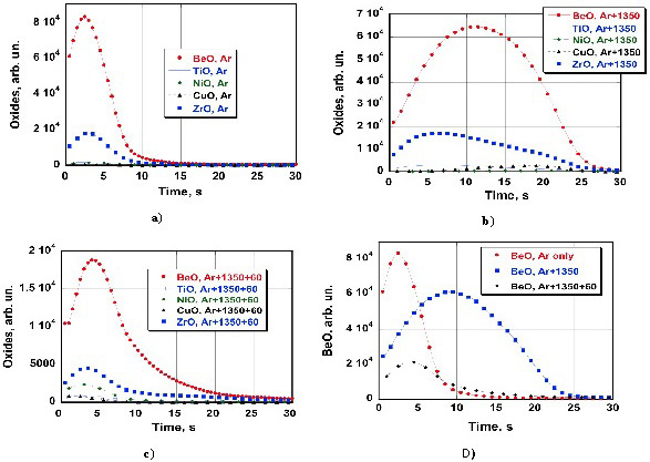 |
Fig. (17). SIMS data for the Zr(46.75)Ti(8.25)Cu(7.5)Ni(10)Be(27.5) alloy samples are given as function of sputtering time of all oxides (a, b, c) and of only beryllium oxide (d) after sputtering by Ar+ ions (a), and after exposure to deuterium plasma ions of energies 1350 eV (b) and 60 eV (c). |
The mechanism of the reflectance decrease may qualitatively differ (partially or fully) from the mechanism for Al and Be mirrors. At deuterium interaction with W and Mo mirrors, a transformation occurs of surface transparent oxide layers WO3 or MoO3, respectively, into so-called “hydrogen bronze” DxWO3 or DxMoO3 (e.g., [49, 50]). Unlike oxide properties, these layers with hydrogen as their constituent exhibit electrical and optical properties, which are dependent on the hydrogen concentration. For example, the conductivity of HxWO3 may increase by more than seven orders of magnitude as the hydrogen content increases from x=0 up to x=0.4 [51], which undoubtedly leads to a reflectance variation. In other words, the characteristics of the oxide film is transformed from dielectric into nearly metallic.
3.5. Copper, Molybdenum and Stainless steel Mirrors in the Tore Supra Tokamak
Experiments on exposure of Cu, Mo and SS mirror samples in the Tore Supra (TS) tokamak [52, 53] have resulted in the discovery of a new effect of mirror interaction with a carbon-containing plasma. The mirrors were arranged close to each other and were open to the plasma during the whole time of their presence in the tokamak chamber, except for a narrow edge around the periphery of the samples, which was closed by the sample holder. This made it possible to perform well calibrated measurements of the layer thickness sputtered under the action of plasma. The greater part of the sample residence time in the tokamak chamber was during wall cleaning procedures by fixed-parameter glow discharges in deuterium or helium. The experimental data on the sputtered layer thickness of the various samples are presented in Table 3.
An important peculiarity of these data is a very low (1.8) experimental value of the ratio of the SS mirror erosion depth to the erosion depth of the Mo mirror. This ratio is nearly a factor of 4 less in comparison to the ratio of SS-to-Mo sputtering coefficients at ion energies typical for glow discharges in TS. During the campaign the anode voltage at operation with helium was +300 V, and with deuterium +400 V. For the corresponding range of ion energy, according to [5], the ratio of sputtering yields Y(SS)/Y(Mo) has to be ~7. An even stronger difference in erosion depth was found for Cu and SS samples: the sputtering coefficients ratio should be Y(Cu)/Y(SS)≡2.5 [5], whereas the obtained ratio of sputtered layer thicknesses equals 12.4.
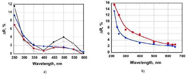 |
Fig. (18). Spectral dependence of the difference between initial reflectance and the reflectance after short-term exposure to deuterium plasma ions widely ranging in energy (50 to 1350 eV) for four SC Mo mirrors (a) and two SC W mirrors (b). |
Sputtering of mirror samples in the TS.
| Mirror Material | Average Roughness Ra, nm |
Sputtering Depth, µm | Sputtering Depth in Relation to the Sputtering Depth of the Mo Sample | ||
|---|---|---|---|---|---|
| Before | After |
Measured Data Y/Y(Mo) |
Computed Results Y/Y(Mo)* | ||
| Mo | 0.5 | 0.7 | 0.12 | 1.0 | 1.0 |
| SS | 1.6 | 5.7 | 0.22 | 1.8 | 6.9 |
| Cu | 7.0 | 47 | 2.68 | 22.3 | 15.5 |
Qualitatively similar results were obtained later when exposing mirrors of the same metals in the LHD facility [54]: 1.1 for ratio of SS and Mo erosion depths and 15.5 for the ratio of Cu to SS erosion depths, instead of ~7 and ~2.5, according to data in [5], correspondingly.
It was assumed in [53] that in the presence of a graphite limiter in TS, the main reason for the low sputtering of the SS mirror was a high probability of carbide formation on the mirror surface exposed to a plasma comprising carbon ion admixtures, because all main components of stainless steel (Fe, Cr, Ni) are capable of forming stable carbides. During exposure to the carbon ion-admixed plasma, a thin carbon film, having a lower sputtering coefficient (e.g., see ref [55]), is continuously formed, strongly reducing the sputtering of the metal mirror.
Unlike stainless steel, copper has no stable carbides, and therefore, on exposure to carbon ion-containing plasma the copper mirror shows no film that includes carbon. The copper surface is sputtered by both deuterium (helium) ions and carbon ions. As a result, the surface roughness develops to very high values of 47 nm, as is seen from Table 3.
To verify this hypothesis, a special experiment was made to investigate the behavior of SS and Cu mirror samples in a methane-containing deuterium discharge [56]. After long-term exposure in a deuterium discharge mixed with 3.5% of methane the SS mirror got coated with a rather thick carbon film, which started to flake off after it was exposed some time in air. In contrast, the copper mirror remained clean, but fully lost its reflectance properties because of severe erosion (Fig. 19).
4. Simulation of the effect of ion bombardment for self-damaged metal mirrors
According to previous [57, 58] and recent [59] calculations, the high-energy neutron-induced effects in the mirror material can be simulated by bombarding the mirrors with MeV-energy ions. To prevent changes in the chemical composition of the mirror near-surface layer, these should be ions of the same metals, from which the mirror is made [18, 22]. Therefore, in our experiments the copper mirror was exposed to a flux of Cu+ ions of energies between 1 to 3 MeV, the stainless steel mirrors - to Cr+ ions, and the aluminum mirror – to Al+ ions of the same energy range, while tungsten mirrors were exposed to W6+ ion fluxes accelerated up to 20 MeV. Based on the energy distributions of charge exchange atoms, measured at the PLT, ASDEX-Upgrade and JFT-IIU facilities, and also, relying on data obtained by simulation [4], nearly all mirrors, except tungsten mirrors, were bombarded by deuterium plasma ions that have a wide energy spectrum from 50 eV up to 1350 eV.
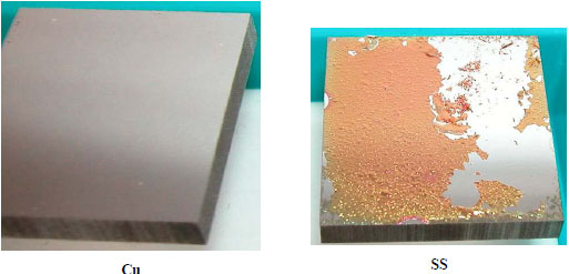 |
Fig. (19). Appearances of Cu and SS mirrors after long-term exposure to a 96.5% deuterium+3.5% methane plasma. The carbon film on the SS started to flake off after exposure to air. In the figure the pristine SS mirror surface is visible in the parts where the layer has flaked off. |
These simulation experiments have shown that neutron radiation alone does not cause appreciable changes in the reflectance R(λ) even at doses up to ~10 dpa (displacements per atom), which substantially exceeds the level expected in ITER during its full life time (typically 0.7 dpa [60]). This result was later qualitatively confirmed by direct neutron radiation experiments, where a Mo corner cube retro-reflector was exposed for a long time in a Japanese nuclear reactor [61].
However, it appears more important to investigate the simultaneous action of both neutrons and charge-exchange atoms. Experiments simulating this situation were performed with Cu, SS and W mirror samples. It was found [10, 18, 22] that within the neutron doses expected in ITER the degradation of optical properties during a long-term sputtering by deuterium plasma ions was practically independent of the fact whether the mirror had been previously exposed to metal ions of MeV energies or not.
As an example, Fig. (20) shows specular reflectance at a wavelength of 600 nm (at normal light incidence) as a function of the thickness of the layer sputtered by 600 eV argon ions for the mirror samples made from tungsten of two types: recrystallized (W-rc) and ITER-grade (W-Ig). One side of each sample was exposed to 20 MeV W+6 ions, while the other side served as an unexposed reference sample. It can be seen from the figure that for both sides of the samples (exposed and unexposed to W+6 ions) there is no appreciable difference in the reflectance behavior.
5. Mirror protection against deposition of contaminating layers and cleaning from deposit
5.1. Mirror Protection Against Deposition of Contaminating Layers
The analysis of data from experiments in which mirrors were exposed inside different fusion devices has shown (see review [62]) that attempt to reduce the influence of the plasma on the mirror through the use of a simple protection (e.g. plane or cylindrical diaphragms) leads to another adverse result: a contaminating film composed of carbon, oxygen and wall materials started to appear on the mirror surface. The reflectance degraded due to contamination of the mirror surface with material eroded from in-vessel components, including the mirror diaphragm, and not due to sputtering. In contrast, the mirrors fully open and exposed to the plasma largely retained their optical properties, provided that the roughness due to sputtering by charge exchange atoms had no time to develop during working discharges and/or by ions during conditioning discharges. Qualitatively similar results were obtained in a comprehensive program to study the behavior of in-vessel mirrors at two versions of JET, with carbon walls [31] and with all metal walls [32].
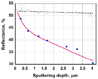 |
Fig. (20). Change of normal incidence reflectance at λ=600 nm for W recrystallized (squares) and ITER-grade (solid circles) A.L.M.T. Corp. specimens not irradiated (lines) and irradiated with 20 MeV W+6 ions to 3 dpa (symbols) on the depth of the layer sputtered by 600 eV Ar ions. |
In case of a first mirror arrangement as shown in Fig. (1), the FM surface may gradually become contaminated either by the material of walls of the diagnostics channel (if they are clean) or by a deposit composed of wall material. In papers [22, 63] a first attempt has been made to describe qualitatively the mechanism by which the deposition may appear and gradually grow on the FM surface. With known data on material sputtering as basis [5, 64], simple estimations were made for the deposition growth rate versus the angle of incidence of sputtering atoms and their energy, and also, versus the relationship between the channel length and diameter.
Fig. (21a) shows schematically how the mirror at the channel end (“bottom”), facing the plasma confinement volume gets contaminated. In ITER this is the first mirror located at the end of the diagnostic duct (Fig. 1). The sputtering agents here are the charge exchange atoms (in the thermonuclear reactor, these are deuterium and tritium atoms), which have a high energy component sufficient for sputtering the wall material. It is obvious from the scheme (Fig. 21a) that the CXA are incident on the channel wall surface at large angles to the normal, provided that the channel is longer than its diameter. And, as known [64], in this case the flux of sputtered particles substantially increases in comparison with the incidence along the normal, reaching its peak value at approximately 80°. At a sufficiently long channel, only an insignificant part of CXA bombards directly the channel “bottom” surface and sputters away the deposition, so from the estimates in [63] it follows that owing to the wall sputtering, the deposition growth rate considerably exceeds the rate of sputtering by the plasma particles directly arriving the “bottom” of the channel without collision with the channel walls.
The estimations given in [63] show that the relationship between the number of particles sputtered from the channel wall in the direction of the “bottom” surface and the particles deposited onto the “bottom’ can be changed either by making the channel much longer than its diameter, or by considerable shortening it in comparison to the diameter. The first case can be marked as “passive protection”, when particles sputtered from the channel walls are again redeposited on the walls closer to the “bottom” but not on the “bottom” surface itself. The second case can be marked as “active protection”, when sputtering of the “bottom” coating by CXA exceeds the deposition of particles eroded from short channel walls. The case with fully open mirrors is an extreme case when there are no channel walls at all. A high efficiency of CXA in providing suppression of deposit growth on fully open mirrors was shown in mirror experiments in several fusion devices, e.g., Tore Supra [19], TEXTOR [20], LHD [54, 65].
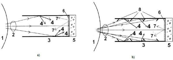 |
Fig. (21). (a) Scheme of contaminating deposit appearance on the diagnostic channel “bottom” (i.e., on the optical window or the mirror). 1 – peripheral plasma; 2 – CXA flux; 3 – diagnostic channel; 4 – approximate trajectories of sputtered atoms of the diagnostic channel material (or a channel wall deposit); 5 – diagnostic window or mirror; 6 – deposit on the mirror; 7 – approximate trajectories of sputtered mirror deposit atoms. (b) Scheme of how the deposit thickness growth rate can be reduced. The notation 1 to 7 is the same as that for Fig. (22a) 8 – diaphragm from a material with a low sputtering coefficient (e.g., tungsten). |
From the above description on how a deposit layer is growing on the “bottom” surface a simple solution follows as to how to substantially reduce the deposit growth rate, or to eliminate the appearance of the deposit at all. For this purpose, it is necessary only to reduce the flux of sputtered atoms from the channel walls reaching the “bottom” surface, to a level lower than the flux of atoms sputtered off from the “bottom” surface by the CXA that arrive from the plasma without collisions with the walls. Qualitatively the same, but a somewhat more complicated structure of the channel is shown Fig. (21b). Here two things are of importance: 1) the diaphragm material must have a low sputtering coefficient (tungsten is best suited for this), and 2) the number of diaphragms and their diameters must be such that there is no direct path of the particles sputtered from the wall to the FM (window) surface.
Recently, a scheme qualitatively similar to that shown in Fig. (21b), has been successfully tested at the Large Helical Device (Toki, Japan) with a simpler shape of fins [54]. It has strongly reduced the mirror contamination, even though stainless steel was used as a material for the diaphragms.
5.2. Removal of Deposited Film
Until recently, carbon-carbon composites have been considered in ITER as material for the divertor target plates (with a total area of 50 m2). Experience of using graphite structural components at numerous fusion devices has shown that additional to charge-exchange atom sputtering, the deposition of carbon-containing film might be another reason of mirror degradation. This is due to the fact that carbon forms volatile molecules with both hydrogen and oxygen, and these molecules may propagate through the vacuum chamber. The threat of carbon deposition is particularly serious for plasma diagnostics mirrors in the divertor region, where the energy of ions and atoms will be low. According to calculations as well as experimental measurements, a pure carbon film of ~10 nm in thickness, can substantially change the spectral reflectance of any metal mirror.
The thickness of carbon-based deposits measured on in-vessel mirrors exposed in the Large Helical Device (LHD), Tore Supra and TRIAM-1M varied in the range 1-50 nm [65]. Therefore, it was necessary to find efficient methods of removing the carbon film directly in-situ in the reactor. One of the methods studied was the usage of a low-temperature hydrogen (deuterium) plasma produced in conditions of electron cyclotron resonance (ECR). It was demonstrated [17] that owing to chemical reactions leading to volatile molecules, this plasma appears highly efficient in removing the carbon film (see Fig. 22) without degradation of the mirror optical properties because of the low ion energy.
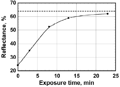 |
Fig. (22). Reflectance recovery (λ=650 nm) of a SS mirror during carbon film (initial thickness ~ 22 nm) removal on exposure time of the mirror to low-energy deuterium plasma. The dashed line shows the reflectance of the clean mirror [17, 70]. |
A similar procedure with exploitation of a low temperature ECR plasma was successfully used to remove a carbon layer that appeared during exposition of mirrors in the LHD heliotron [66], the TRIAM-1 tokamak [67], in the test stand DSM-2, and similarly, of mirrors exposed in DIII-D and TEXTOR in the toroidal stand TOMAS [68]. A high efficiency of chemical cleaning of hydrocarbon films was demonstrated in ref [69].
Another result that follows from Fig. (22) is that with a decrease in the film thickness, the film erosion rate gradually decreases. This is due to the formation of carbides directly on the SS surface. These are more resistant to the action of hydrogen atoms and ions.
The decision to exclude carbon as a structural in-vessel material in ITER had a considerable effect on the methods that can be utilized for mirror cleaning. This was evident from experiments with full metal walls in ASDEX [71] and JET [32]. Namely, in both devices the mirror specimens in the divertor region and at the outer wall of the main vessel were coated with a deposit that included tungsten, the main material of the divertor tiles. In the case of JET beryllium was one of the main components along with carbon and oxygen [32].
It is not possible to clean mirrors from metal-containing deposits by chemical erosion, as in the case of a hydrocarbon film. At present two methods are under thorough investigation: cleaning by a pulsed laser (e.g., [72, 73] and cleaning by a plasma [74-76]. These techniques have been first tested on their efficiency to remove carbon and hydrocarbon films from the mirrors.
The first successful attempt to clean a mirror exposed in a fusion device (the T-10 tokamak) by a pulsed laser was described in ref [70]. Because of the graphite limiter in use during that experiment, the film was composed of a carbon–hydrocarbon mixture. After removing the samples from the T-10 vessel a full recovery of the initial reflectance of the mirrors was achieved by exposing it to a pulsed excimer laser (λ=308 nm, pulse duration τ=20 ns, repetition frequency f=10 Hz).
The first attempt to clean a Be-containing film was undertaken by the authors of [77]. For cleaning SS and Mo mirrors exposed in JET during 2005-2007 a laser with λ=1064 nm, pulse length τ=120 ns and repetition rate 20 kHz was used. The initial reflectance was not reached for any of the ten mirror specimens tested. Later, single crystal Mo specimens exposed inside the JET vacuum vessel (mainly in the divertor area) during the 2008-2009 campaign were subjected to cleaning with a much shorter laser pulse duration: wavelengths 230, 532 and 1064 nm, pulse length τ=5 ns and repetition rate 20 Hz [78]. For some specimens that had an initially thin contaminating deposit (10-15 nm) a full restoration of the reflectance was achieved.
The experimental results revealed some technical difficulties of laser assisted mirror cleaning. To optimize the process of cleaning, at least five parameters have to be taken into account: laser wavelength λ, pulse duration, laser fluence, pulse repetition rate, and the rate of laser spot scanning along the mirror surface.
In experiments with plasma cleaning of a metal-containing deposit [74-76] aluminium was used as proxy of beryllium to avoid problems with the toxicity of beryllium in laboratory conditions.
In [76] cleaning of an Al (80 nm)+Al2O3 (20 nm) film deposited on a single crystal Mo mirror was realized by exposing it in the TOMAS toroidal facility operating with a steady-state ECR-generated He plasma (ne~3·1010 cm-3 and Te~5 eV) at 2.45 GHz. The plasma ions were accelerated to the mirror by applying a negative voltage -100 V).
The authors of [74, 75] investigated the cleaning of a mirror surface from a deposit composed of Al, Al2O3, and W by the use of plasma with as working gas: Ar, Ne or a Ar+D2 mixture. The most effective in this respect was the Ar plasma produced by a RF capacitively coupled discharge (at frequency 13.56 MHz) with the test mirror utilized as an electrode. In some cases a full cleaning of deposits with initial reflectance restoration was achieved. For the first time a mirror with a size (98 mm in diameter) close to the size of a real first mirror in ITER was successfully cleaned from deposition by a 260 nm thick Al/Al2O3 film on its surface [74]. This result is very important when considering the prospects for application of both these techniques (laser and plasma) to remove the contaminating layers from mirror surfaces in ITER environment. With a plasma a large size mirror can be subjected to the cleaning process at once, which results in more homogeneous optical properties along the surface.
The best results with plasma cleaning are expected when the mirror is made of single crystalline metal to avoid the appearance of surface roughness due to sputtering away the contaminating layer by plasma ions.
5.3. Removal of Metal Oxides
Experiments with mirrors of different types have added much to the results of paper [79] concerning the efficiency of removing oxide films of different thickness (δ) through the use of low-temperature hydrogen plasma, as is shown in Table 4. All new data (for BeO, Al2O3, WO3 in comparison with the ones of ref [79]) were obtained by applying optical and ellipsometric methods in experiments with metal mirrors (Be, Al, W) and film mirrors (Al, Ag) protected with a dielectric film (Al2O3, ZrO2). The data of Table 4 testify that copper oxide is the most easily removable film, while zirconium oxide film appears the most stable.
5.4. In Situ Inspection of in-vessel Mirror Degradation
To ensure good optical quality of the in-vessel mirrors in ITER during experimental campaigns it is necessary to regularly monitor their optical characteristics. In order to assess whether or not the mirrors can be cleaned one must distinguish between the appearance of a contaminating deposit and the development of surface roughness. In the first case the mirror can be cleaned (e.g. by methods indicated in Sec. 5.2) with restoration of reflectance, but in the second case the measurement results need to be permanently corrected, if mirror cannot be replaced.
One possibility to find the reason why the mirror optical properties have degraded was proposed in ref [45]. The method is based on the analysis of the image of a light source with sharp edges transmitted by the mirror under investigation. In the case the mirror has a deposit of a contaminating film,the reflectance decreases but the edges of the image will continue to be sharp without any diffusive component. In contrast, the appearance of wings in the light source image would indicate the development of surface roughness. The amplitude of the wings increases with increasing roughness of the mirror surface.
The feasibility of this method was demonstrated by its application to mirror specimens coated with carbon film in laboratory conditions and to mirrors coated with contaminated films as a result of exposure of the mirrors in LHD, TRIAM-1M, and Tore Supra. The characteristics of these films are described in refs [65, 66], and [53], respectively.
Efficiency of metal oxide removal by exposure to a hydrogen plasma produced under conditions of electron cyclotron resonance, according to the data of ref [79] and the recent data of refs. [43, 46, 48, 80] (as indicated in the last column).
| Metal | Oxide | Thickness δ, nm | Time, h | Removal Efficiency, O at/103 H at | Reference |
|---|---|---|---|---|---|
| Cu | Cu2O | 150 | 0.02 | ~750 | [79] |
| Ni | NiO | 209 | 3 | 7.9 | [79] |
| Fe | Fe2O3 | 153 | 5 | 3.3 | [79] |
| Mo | MxOy | ~100* | 6 | ~3* | [79] |
| Ti | TiO2 | 177 | 15 | 2.0 | [79] |
| Be | BeO | ~17 | 1.5 | ~1 | [43] |
| Al | Al2O3 | ~8 | ~0.5 | [46] | |
| W | WO3 | ~10 | 2.0 | ~0.5 | [48] |
| Zr | ZrO2 | ~14 | 30 | ~0.15** | [80] |
| Zr | ZrO2 | ~14 | 30 | ~0.7*** | [80] |
The effect of long term sputtering by plasma ions on the appearance of diffusive components was studied for mirrors of different materials by the use of the DSM-2 stand (in IPP NSC KIPT). Fig. (23) shows an example of in situ measurements of wings growing under permanent sputtering of a Cu mirror specimen [45]. The thickness of the sputtered layer was estimated by measuring the mass loss after finishing the experiment, under the assumption that the sputter rate does not depend on the sputtering time, which was proven experimentally.
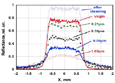 |
Fig. (23). In situ results obtained when a polycrystalline Cu mirror was gradually sputtered inside the DSM-2 stand. Initially the reflectance raised due to cleaning from oxide and then started to decrease due to roughness development. |
6. Influence of recurrent laser pulses
The Thomson scattering diagnostic in the ITER main chamber will make use of pulsed laser radiation with a rather high pulse-repetition frequency (~30 pulses per second), at laser radiation energy of ~5 J and a pulse length of 20-30 ns. During the whole period of ITER operation there will be approximately 104 working discharge pulses of 400 s length, so the total number of laser pulses will reach ~108. As was found in many publications (see survey [81]), with recurring laser pulses the threshold for laser mirror destruction, FN, substantially decreases: the more pulses (N) the mirror has to cope with, the lower should be the energy of each pulse in comparison with the threshold for a single laser pulse, F1. The relationship between the two thresholds essentially depends on the mirror material, as was shown, e.g., in [70] Fig. (24).
The measurement data at N≈1.5x10⁵ pulses for W, Mo and Cu mirrors and their extrapolation up to N=108 are shown in Fig. (24) as the ratio FN/F1versus N, which satisfies the relation FN = F1NS-1 with S=0.82 for W, S=0.86 for Cu, and S=0.89 for Мо. As can be seen, the Mo mirror shows an appreciably lower FN degradation rate with an increase of the number of laser pulses. However, for a long-term service life of the laser mirror the absolute value of FN is of importance, and in this relation copper has a significant advantage, viz., after 108 pulses its F8 will be equal to ~1.0 J/cm2, whereas for the Mo mirror F8 ≈ 0.4 J/cm2.
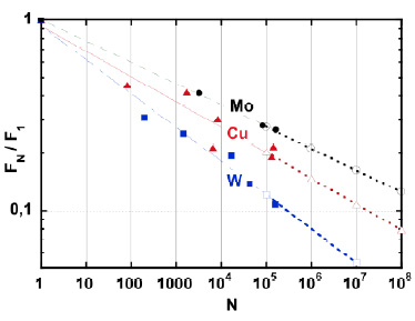 |
Fig. (24). Threshold of mirror surface layer degradation at exposure to multi-pulse laser radiation (wavelength 1.06 µm) as a function of the number of pulses for SC (Mo and W) and PC Cu mirrors, as found experimentally up to N≈1.5x10⁵ (solid points) and approximated up to 108 pulses (open points). The measured thresholds are: F1 = 3±0.5 J/cm2 for Мо, F1 = ~15 J/cm2 for Cu, and F1 = 6.5 ± 0.8 J/cm2 for W [70]. |
A detailed analysis of different metals (Au, Ag, Cu, Ta, Rh, and Mo) as candidate materials for laser mirrors has been carried out in ref [82]. The results of numerical calculations have shown that copper is only slightly inferior to silver and gold in its optical and thermomechanical properties. However, it is much cheaper and easier to manufacture high-grade mirrors from Cu.
7. On the use of the Bennett formula
To estimate the surface roughness stemming from metal mirror erosion, the Bennett formula [83] is frequently used:
where Ro is the reflectance of the ideally smooth surface for normal incidence of light, λ is the wavelength of radiation reflected from the given mirror surface with the reflectance R, and d is the average roughness of the surface. The Bennett formula was derived for a rough surface, with a height distribution that can be described by a Gaussian formula.
In fact, in most cases, as far as the metal mirror sputtering is concerned, the surface relief has quite a different character. For example, in case of polycrystalline material, the surface may become stepwise (Figs. 2, 3, 5 of the present paper, Fig. (1) in [7], Figs. (1-3) in [8], Fig. (13) in [18]), or etch pits may appear (Fig. 2b in [53]), “ridges and valleys” (Fig. 4 in [11]), etc.
In all cases, it is reasonable to make sure whether formula (1) can be used for roughness estimation. This can be done by applying the expression formally for different wavelengths. If the derived roughness values do not differ too much between themselves, then this will be indicative of the validity of the formula for describing the relief of the given mirror and obtaining a reasonably correct mean roughness characteristic.
We give several examples of the approach.
Fig. (25) shows typical data for a copper mirror (a) and for stainless steel mirrors (b) after sputtering of 2.5 μm and 4 μm thick layers, respectively. The data of Fig. (25b) are given for the same mirror specimens, of which the degradation of optical properties is shown in Fig. (4). In both cases (Figs. 25a and b), the relief was typically stepwise: with a more shallow relief in certain grains of the copper mirror (Fig. 4 in [6]) and practically no relief in the grains of SS steel mirrors (Fig. (1) in [7] and Fig. (13) in [18]).
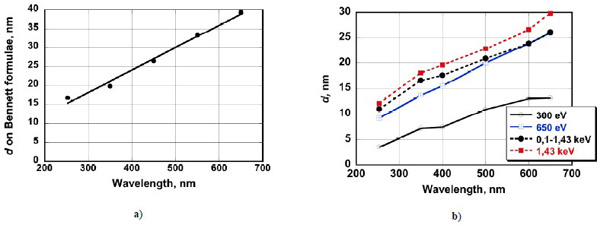 |
Fig. (25). Mean surface roughness d derived by formula (1) for mirror samples from copper (a) and stainless steel (b). The legend in b gives the deuterium plasma ion energies for the samples under exposure. |
As is evident from the given data, for polycrystalline mirrors the mean roughness is not the same at different wavelengths, because the stepwise surface structure by no means corresponds to the conditions, for which the Bennett formula was derived.
Similar results were obtained with many mirror specimens fabricated as metal film on metal substrate, in spite of the typical small size crystallite structure. Among the many film mirrors studied, not all mirrors showed a divergence between the roughness values calculated for different wavelengths to vary in a narrow range. As an example of the surface roughness that can be described by the Bennett formula, Fig. (26) shows the mean roughness values, calculated by the formula for one of the samples of the “Rh film on a copper substrate” at different wavelengths. It is obvious that for this sample the roughness of the type under discussion began to form already at an early stage of sputtering (Fig. 26a). Three more examples of satisfactory agreement between the roughness values of similar film samples for different wavelengths have been described in ref [35].
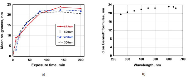 |
Fig. (26). Mean surface roughness d values derived by formula (1) for one of the “Rh film on a copper substrate” mirror samples versus sputtering time (a) and versus the wavelength after the last exposure to the plasma (b). |
As evidenced by the results of numerous experiments with mirrors of different structure, it is impossible to foresee the character of the relief, which will appear on the surface after long-term sputtering.
Conclusion
During many years of metal mirror performance studies under conditions approximating the mirror operating conditions in the experimental fusion reactor ITER many data have been collected in the Ukraine, sometimes in close cooperation with international collaborators. The main results have been reviewed in this paper and are summarized below.
Systematic simulation experiments were performed to study the behavior of polycrystalline metal mirrors (Be, Al, SS, Cu, Ti, Mo, W, Ta), single-crystalline mirrors (SS, Ni, Mo, W), film-type mirrors (film/substrate, i.e., Be/Cu, Cu/Cu, Rh/Cu, Rh/V, Rh/SS, Mo/SS, Mo/Mo) and mirrors from amorphous alloys of ZrTiCuNiBe type during long-term sputtering by deuterium (in some cases, argon) plasma ions.
The main results obtained can be divided into two groups: results directly relating to plasma diagnostics in ITER and results having a common scientific significance.
To the first group the following results can be designated:
- Single crystal mirrors have a substantial advantage over polycrystalline mirrors thanks to their much higher resistance against surface roughening due to sputtering. After confirmation of this result in operating fusion devices it was decided by the ITER community to use single crystal Mo as the material choice for most first mirrors.
- The prospect of Rh film to be of interest as material for in-vessel mirrors was shown for the first time.
- Results of experiments to mimic the simultaneous impact of neutron radiation and charge-exchange atoms on mirrors made of Cu, SS, and W showed that there is no synergetic effect for the ITER case, which is good news.
- A model to qualitatively explain the appearance of a contaminating deposit layer on a mirror located inside a diagnostic channel was developed. On the basis of the model it was concluded that the mirror can be protected from contamination either by fully opening it to CXA flux or by placing it in a channel with fins to reduce the flux of atoms sputtered from the walls to reach the mirror.
- A method to distinguish in situ the reason for the degradation of mirror optical properties, i.e. sputtering or deposition, was suggested and successfully tested at the test stand DSM-2.
- Taking into account the necessity of using laser methods for plasma diagnostics in ITER, an analysis has been made of the impact of laser radiation with pulses recurring every ~30 ms on mirrors made from different metals. It has been found that for a total number of laser pulses greater than or equal to 108, copper will be the best mirror material.
- Experimentally it was shown that both sputtering of a polycrystalline mirror as well as deposition of a contaminant results in a change of polarization of reflected light beam in comparison to a clean mirror surface. For diagnostic methods that rely on the polarization of the observed light, this effect should be taken into account
- Application of the Bennett formula to describe the roughness that develops on a polycrystalline mirror under sputtering was analyzed. A simple procedure to estimate whether the formula can be applied was suggested.
The results in this paper give some guidance and input to the FM problem in ITER. It is difficult to give in our paper a recipe which mirrors are to be preferred for application and location in the ITER vessel. The main reasons for this arise from: (i) the exact designs of the different ITER diagnostics that are being developed by different groups of specialists are difficult to obtain, and (ii) several of the characteristics of the damaging factors impacting the mirror surface (first of all, energy and flux of charge exchange atoms) are not precisely known. The FM problem of ITER deserves the attention of the worldwide community of researchers in the field of first mirrors.
To the second group the following results can be designated:
- The studies of hydrogen plasma interaction with mirrors from Be, Al, Cu, Mo, W and amorphous alloys have revealed the importance of chemical processes occurring on the metal surface, which cause changes in the optical properties of the mirror during exposure to both pure hydrogen plasma ions and plasma admixed with oxygen. Based on the analysis of experimental results from studies of different-structure polycrystalline metal mirrors, a model for the mirror surface roughening during long-term sputtering has been developed.
- It was found in experiments with polycrystalline Cu and SS mirrors that the difference in sputtering rate of differently oriented grains significantly increases with increasing ion energy.
- A unique resistance of amorphous-alloy mirrors to surface roughening under long-term sputtering over mirrors of any other type was attributed to the absence of any ordered structure at a level greater than a few nanometers.
The most important results of these investigations were confirmed by collaborative studies made at large fusion devices such as the tokamaks TEXTOR (Julich) in Germany, Tore Supra (Cadarache) in France, small size tokamak TRIAM-1M (Fukuoka) in Japan and the Large Helical Device (Toki) in Japan. The conclusion from results of our simulation experiments about the absence of the neutron radiation impact on the optical properties of metal mirrors was confirmed by experiments with Mo corner cube retro-reflector at the Japanese experimental nuclear reactor. The idea to use a number of metal diaphragms to protect the mirror in a diagnostic channel from contamination was supported by experiments in Large Helical Device (Toki, Japan).
CONFLICT OF INTEREST
The authors confirm that this article content has no conflict of interest.
Acknowledgements
The authors would like to express deep thanks to their colleagues with whom the majority of the enumerated results were obtained and published: D.V. Orlinski, V.G. Konovalov, S.I. Solodovchenko, A.N. Shapoval, A.F.Shtan’, V.N. Bondarenko, I.V. Ruzhkov, O. Skoryk, M. Balden, M.F. Becker, A.I. Belyaeva, A.E. Costley, J.W. Davis, N. Klassen, K.V. Kovtun, M. Lipa, A. Litnovsky, E.E. Mukhin, L.V. Poperenko, A.G. Razdobarin, B. Schunke, A. Sagara, G. De Temmerman, K. Y. Vukolov. We acknowledge financial support of experiments with Be and amorphous mirror specimens within the framework of STCU project 3668.
References
| [1] | www.iter.org |
| [2] | Donné AJ, Costley AE, Voitsenya V, et al. Diagnostics. Nucl Fusion 2007; 47: 337-84. |
| [3] | Vayakis G, Hodgson ER, Voitsenya V, et al. Generic diagnostic issues for a burning plasma experiment. In: Costley AE, Johnson DW, Eds. Fusion Science and Technology. 2008; Chapter. 12: pp. 699-750. |
| [4] | Behrisch R, Federichi G, Kukushkin A, et al. Material erosion at the vessel walls of future fusion devices. J Nucl Mater 2003; 313-316: 388-92. |
| [5] | Yamamura Y, Tawara H. Energy dependence of ion induced sputtering yields from monoatomic solids at normal incidence. At Data. Nucl Data Tables (NY) 1996; 62: 149-253. |
| [6] | Bardamid AF, Gritsyna VT, Konovalov VG, et al. Ion energy distribution effects on degradation of optical properties of ion-bombarded copper mirrors. Surf Coat Tech 1998; 103-104: 365-9. |
| [7] | Bardamid A, Bryk V, Konovalov V, et al. Erosion of steel under bombardment with ions of a deuterium plasma. Vacuum 2000; 58: 10-5. |
| [8] | Balden M, Bardamid AF, Belyaeva AI, et al. Surface roughening and grain orientation dependence of the erosion of polycrystalline stainless steel by hydrogen irradiation. J Nucl Mater 2004; 329-333: 1515-9. |
| [9] | Bardamid AF, Belyaeva AI, Bondarenko VN, et al. Ion fluence and energy effects on the optical properties of SS mirrors bombarded by hydrogen ions. Phys Scr 2003; T103: 109-11. |
| [10] | Voitsenya VS, Balden M, Belyaeva AI, et al. Effect of sputtering on self-damaged recrystallized W mirror specimens. J Nucl Mater 2013; 434: 375-81. |
| [11] | Voitsenya VS, Balden M, Bardamid AF, et al. Development of surface relief on polycrystalline metals due to sputtering. Nucl Instrum Methods Phys Res B 2013; B302: 32-9. |
| [12] | Kawano Y, Chiba Sh, Inoue A. Infrared laser polarimetry for electron density measurement in tokamak plasmas. Rev Sci Instrum 2001; 72: 1068-72. |
| [13] | Donné AJ, Graswinskel MF, Cavinato M, et al. Poloidal polarimeter for current density measurements in ITER. Rev Sci Instrum 2004; 75: 4694-701. |
| [14] | Voitsenya VS, Donné AJ, Bardamid AF, et al. Simulation of environment effects on retroreflectors in ITER. Rev Sci Instrum 2005; 76: 083502. |
| [15] | Yoshida N, Ohtawa Y, Ebihara A, et al. Reflectivity Reduction of Retro-Reflector Installed in LHD due to Plasma Surface Interaction 2008. 22nd IAEA Fusion Energy Conference; 13-18 October; Geneva, Switzerland. 2008. Available from: http://www.nifs.ac.jp/report/ NIFS-923.pdf |
| [16] | Malaquias A, von Hellermann M, Lotte P, Tugarinov S. VS Polarization and reflectivity changes on mirror based viewing systems during long pulse operation 2003; 30th EPS Conf Contr Fusion Plasma Phys; 7-11 July; St. Petersburg, Russia; ECA. 2003; pp. 27A: 0-3.4C. Available from: http://www.iaea.org/inis/collection/NCLCollectionStore/_Public/36/023/36023933.pdf |
| [17] | Voitsenya V, Costley AE, Bandourko V, et al. Diagnostic first mirrors for burning plasma experiments (Invited). Rev Sci Instrum 2001; 72: 475-82. |
| [18] | Orlinski DV, Voitsenya VS, Vukolov KY. First mirrors for diagnostic systems of an experimental fusion reactor. I. Simulation mirror tests under neutron and ion bombardment. Plasma Devices Oper 2007; 15: 33-75. |
| [19] | Lipa M, Schunke B, Gil CH, et al. Analyses of metallic first mirror samples after long term plasma exposure in Tore Supra. Fusion Eng Des 2006; 81: 221-5. |
| [20] | Litnovsky A, De Temmerman G, Vukolov K, et al. Investigations of single crystal and polycrystalline metal mirrors under erosion conditions in TEXTOR. Fusion Eng Des 2007; 82: 123-32. |
| [21] | Bardamid AF, Vukolov KY, Konovalov VG, et al. The test of Mo and W mirrors under the long-term bombardment by ions of deuterium plasma. Plasma Dev Oper 2004; 12: 203-8. |
| [22] | Voitsenya VS, Bardamid AF, Becker MF, et al. Some problems of the material choice for the first mirrors of plasma diagnostics in a fusion reactor. Rev Sci Instrum 1999; 70: 790-3. |
| [23] | Marot L, De Temmerman G, Oelhafen P, Covarel G, Litnovsky A. Rhodium coated mirrors deposited by magnetron sputtering for fusion applications. Rev Sci Instrum 2007; 78(10): 103507. |
| [24] | Uccello A, Dellasega D, Perissinotto S, et al. Nanostructured rhodium films for advanced mirrors produced by Pulsed Laser Deposition. J Nucl Mater 2013; 432: 261-5. |
| [25] | Mostako AT, Rao CV, Khare A. Mirrorlike pulsed laser deposited tungsten thin film. Rev Sci Instrum 2011; 82(1): 013101. |
| [26] | Marot L, Arnoux G, Huber A, et al. Optical coatings as mirrors for optical diagnostics Accepted in Journal of Coating Science and Technology. Available from: http://www.euro-fusionscipub.org/wp-content/uploads/2015/08/WPJET1PR1535.pdf |
| [27] | Bardamid AF, Vukolov KY, Konovalov VG, et al. Testing of molybdenum film mirrors under bombardment by deuterium plasma ions. Plasma Dev Oper 2006; 14: 159-70. |
| [28] | Eren B, Marot L, Ryzhkov IV, et al. Roughening and reflection performance of molybdenum coatings exposed to high flux deuterium plasma. Nucl Fusion 2013; 53: 113013. |
| [29] | Eren B, Marot L, Langer M, et al. The effect of low temperature deuterium plasma on molybdenum reflectivity. Nucl Fusion 2011; 51: 103025. |
| [30] | Marot L, Oelhafen P, De Temmerman G, et al. Coated mirrors for ITER 2007. Coated mirrors for ITER. Presentation at the 13th meeting of ITPA; October 31,; Chengdu, China. 2007. Available from: https://portal.iter.org/departments/POP/ITPA/Diag/DIAG/Docu ment%20Library/21/Marot.mirrors.pdf |
| [31] | Marot L, Meyer E, Rubel M, et al. JET-EFDA contributors. Performances of Rh and Mo mirrors under JET exposure. J Nucl Mater 2013; 438: 1187-91. |
| [32] | Ivanova D, Rubel M, Widdowson A, et al. An overview of the comprehensive First Mirror Test in JET with ITER-like wall. Phys Scr 2014; T159: 014011. |
| [33] | Vukolov K, Medvedev A, Orlovskiy I. Issues and options for mirrors of CXRS and H-alpha ITER diagnostics. In: Orsitto FP, Gorini G, Sindoni E, Toridocchi M, Eds. In: AIP Conf. Proc.; Varenna (Italy). 2008; pp. 988: 370-4. Available from: http://dx.doi.org./10.1063/ 1.2905101 |
| [34] | Vukolov KY, Mukhammedzyanov TR, Andreenko EN, et al. Plasma tests of diagnostic mirrors for ITER purposes. Fusion Eng Des 2013; 88: 1280-3. |
| [35] | Bondarenko VN, Bardamid AF, Konovalov VG, et al. Effects of long-term ion bombardment on some optical properties of Rh film mirrors and bulk polycrystalline mirrors. Probl At Sci Technol Ser Plasma Phys 2006; 6: 80-3. |
| [36] | Voitsenya VS, Bardamid AF, Belyaeva AI, et al. Modification of optical characteristics of metallic amorphous mirrors under ion bombardment. Plasma Dev Oper 2009; 17: 144-54. |
| [37] | Bardamid AF, Voitsenya VS, Davis JW, et al. Comparison of the behavior of Zr(41.2%)Ti(13.8%)Cu(12.5%)Ni(10%)Be(22.5%) amorphous and crystallized mirrors under deuterium ion bombardment. J Alloys Compd 2012; 514: 189-94. |
| [38] | Peng D, Shen J, Sun J, et al. Kinetic characteristic of hydrogenation Zr-Ti-Cu-Ni-Be Bulk amorphous alloy. J Mater Sci Technol 2004; 20: 157-9. |
| [39] | Cheng X-Y, Wang F. Hydrogen absorption and desorption in metallic glass and nanocrystalline Zr52.5Cu17.9Ni14.6Ti5Al10 alloy. Trans Nonferrous Met Soc China 2009; 19: 377-82. |
| [40] | Arakawa ET, Callcott TA, Yug-Ching C. Beryllium (Be). In: Palik ED, Ed. Handbook of optical constants of solids II. San Diego: Academic Press Limited 1991; pp. 421-33. |
| [41] | De Temmerman G, Baldwin MJ, Doerner RP, et al. Beryllium deposition on international thermonuclear experimental reactor first mirrors: layer morphology and influence on mirror reflectivity. J Appl Phys 2007; 102: 083302. |
| [42] | Voitsenya VS, Bardamid AF, Bondarenko VN, et al. Modification of optical properties of Be mirrors under bombardment by deuterium ions. J Nucl Mater 2004; 329-333: 1476-80. |
| [43] | Bardamid AF, Bondarenko VN, Davis JW, et al. Changes to the reflectance of Be mirrors due to deuterium plasmas contaminated with oxygen. J Nucl Mater 2010; 405: 109-17. |
| [44] | Langley RA. Interaction of implanted deuterium and helium with beryllium: radiation enhanced oxidation. J Nucl Mater 1979; 85-86: 1123-6. |
| [45] | Konovalov VG, Makhov MN, Shapoval AN, et al. The method for in situ monitoring of the quality of in-vessel mirrors in a fusion reactor. Probl Atom Sci Technol. Series Plasma Phys 2009; 1(59): 13-5. |
| [46] | Bardamid AF, Belyaeva AI, Davis JW, et al. Optical properties of Al mirrors under impact of deuterium plasma ions in experiments simulating ITER conditions. J Nucl Mater 2009; 393: 473-80. |
| [47] | Kiene M, Strunskus T, Hasse G, et al. Oxide formation on the bulk metallic glass Zr(46.75)Ti(8.25)Cu(7.5)Ni(10)Be(27.5). Mater Res Soc Symp Proc 1999; (554): 167-72. |
| [48] | Voisenya V, Davis J. Chemical processes on metal surfaces exposed to contaminated hydrogen plasmas. Adv Appl Plasma Sci 2009; 7: 7-12. |
| [49] | Mino G, Hussain Z. Optical properties of dilute hydrogen bronze thin films. J Appl Phys 1991; 69: 7788-96. |
| [50] | Hussain Z. Dopant-dependent reflectivity and refractive index of microcrystalline molybdenum-bronze thin films. J Appl Phys 2002; 91: 703-6. |
| [51] | Griessen R, Huiberts JN, Kremers M, et al. Yttrium and lanthanum hydride films with switchable optical properties. J Alloys Compd 1997; 253-254: 44-50. |
| [52] | Lipa M, Schunke B, Gil Ch, et al. First mirror study in Tore Supra, EFDA ref TW2-TPDS-DIADEV-D02, Final report 12, 01, 2005; Cadarache, France. |
| [53] | Voitsenya VS, Bardamid AF, Belyaeva AI, et al. Interpretation of Tore Supra in-vessel mirror experiments. Plasma Dev Oper 2008; 16: 1-10. |
| [54] | Akiyama T, Yoshida N, Kawahata K, et al. Studies of reflectivity degradation of retroreflectors in LHD and mitigation of impurity deposition using shaped diagnostic ducts and protective windows. Nucl Fusion 2012; 52: 063014. |
| [55] | Bondarenko VN, Belyaeva AI, Voitsenya VS, et al. Experimental and numerical studies of carbon film effect on the optical properties of metallic mirrors. J KNU 2005; 26(1): 47-56. |
| [56] | De Temmerman G, Pitts RA, Voitsenya VS, et al. First mirror tests for ITER: Influence of material choice on the erosion/deposition mechanisms affecting optical reflectivity. J Nucl Mater 2007; 363-365: 259-63. |
| [57] | Kulcinski GL, Laidler JJ, Doran DG. Simulation of high fluence fast neutron damage with heavy ion bombardment. Radic Effects 1971; 7: 195-202. |
| [58] | Abromeit C. Aspects of simulation of neutron damage by ion irradiation. J Nucl Mater 1994; 216: 78-96. |
| [59] | Ogorodnikova OV, Gann V. Simulation of neutron-induced damage in tungsten by irradiation with energetic self-ions. J Nucl Mater 2015; 460: 60-71. |
| [60] | Shimada M, Hatano Y, Oya Y, et al. Overview of the US-Japan collaborative investigation on hydrogen isotope retention in neutron-irradiated and ion-damaged tungsten. Fusion Eng Des 2012; 87: 1166-70. |
| [61] | Nishitani T, Ishitsuka E, Kakuta T, et al. Japanese contribution to ITER task of irradiation tests on diagnostic components. Fusion Eng Des 1998; 42: 443-8. |
| [62] | Voitsenya VS, Litnovsky A. Investigations of mirrors for ITER diagnostics in the modern fusion devices. Plasma Dev Oper 2009; 17: 309-18. |
| [63] | Voitsenya VS. On the mechanism of contamination of diagnostic windows in fusion devices. Rev Sci Instrum 1999; 70: 787-9. |
| [64] | Eckstein W, Garcia-Rosales C, Roth J, Ottenberger W. Sputtering Data 1993. Preprint IPP 9/82, Max-Plank-Institute für Plasmaphysik, Garching bei München, Germany, February |
| [65] | Voitsenya VS, Sagara A, Lipa M, et al. The properties of contaminated films deposited on in-vessel mirrors in Large Helical Device, Tore Supra, TCV and TRIAM-1M 2006; 33rd EPS Conf Contr Fusion Plasma Phys; 19-23 June, 2013; Rome, Italy ECA. 2006; p. 30I: 5.134. Available from: http://epsppd.epfl.ch/Roma/pdf/P5_134.pdf |
| [66] | Voitsenya VS, Sagara A, Belyaeva AI, et al. Effect of exposure inside the Large Helical Device vessel on the optical properties of stainless steel mirrors. Plasma Dev Oper 2005; 13: 291-300. |
| [67] | Litnovsky A, Voitsenya VS, Costley A, et al. First mirrors for diagnostic systems of ITER. Nucl Fusion 2007; 47: 1-6. |
| [68] | Litnovsky A, Laengner M, Matveeva M, et al. Development of in situ cleaning techniques for diagnostic mirrors in ITER. Fusion Eng Des 2011; 86: 1780-3. |
| [69] | Arkhipov I, Gorodetsky A, Zalavutdinov R, et al. Development of plasma cleaning techniques for in-vessel optical components in ITER. J Nucl Mater 2011; 15: 1210-3. |
| [70] | Orlinski DV, Voitsenya VS, Vukolov KY. First mirrors for diagnostic systems of an experimental fusion reactor. II. The mirror tests on the large fusion devices under operation. Plasma Dev Oper 2007; 15: 127-46. |
| [71] | Litnovsky A, Matveeva M, Herrmann A, et al. First studies of ITER-diagnostic mirrors in a tokamak with an all-metal interior: results of the first mirror test in ASDEX Upgrade. Nucl Fusion 2013; 53: 073033. |
| [72] | Wisse M, Marot L, Eren B, et al. Laser damage thresholds of ITER mirror materials and first results on in situ laser cleaning of stainless steel mirrors. Fusion Eng Des 2013; 88: 388-99. |
| [73] | Wisse M, Marot L, Steiner R, et al. Picosecond and nanosecond laser ablation of mixed tungsten/aluminum films. Fusion Sci Technol 2014; 66: 308-14. |
| [74] | Moser L, Steiner R, Leipold F, et al. Plasma cleaning of ITER First Mirrors in magnetic field. J Nucl Mater 2015; 463: 940-3. |
| [75] | Moser L, Marot L, Eren B, et al. Towards plasma cleaning of ITER first mirrors. Nucl Fusion 2015; 55: 063020. |
| [76] | Litnovsky A, Matveeva M, Buzi L, et al. Studies of protection and recovery techniques of diagnostic mirrors for ITER. Nucl Fusion 2015; 55: 093015. |
| [77] | Widdowson A, Coad JP, De Temmerman G, et al. Removal of beryllium-containing films deposited in JET from mirror surfaces by laser cleaning. J Nucl Mater 2011; 415: 1199-202. |
| [78] | Wisse M, Marot L, Widdowson A, et al. EFDA-JET Contributors. Laser-assisted cleaning of beryllium-containing mirror samples from JET and PISCES-B. Fusion Eng Des 2014; 89: 122-30. |
| [79] | Sakamoto Y, Ishibe Y. Reduction of metal oxides by electron cyclotron resonance (ECR) plasma of hydrogen - a model study on discharge cleaning. Jpn J Appl Phys 1980; 19: 839-43. |
| [80] | Razdobarin AG, Mukhin EE, Semenov VV, et al. Diagnostic mirrors with transparent protection layer for ITER. Fusion Eng Des 2011; 86: 1341-4. |
| [81] | Voitsenya VS, Konovalov VG, Becker MF, et al. Materials selection for the in situ mirrors of laser diagnostics in fusion devices. Rev Sci Instrum 1999; 70: 2016-25. |
| [82] | Kajita Sh, Hatae T. Voitsenya VS. Assessment of laser transmission mirror materials for ITER edge Thomson scattering diagnostics. Plasma Fusion Res 2008; 3: 32-7. |
| [83] | Bennett HE. Specular reflectance of aluminised ground glass and the height distribution of surface irregularities. J Opt Soc Am 1963; 53: 1389-94. |