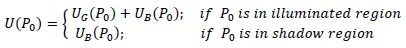
RESEARCH ARTICLE
Step-by-step Evolution of Young’s Double-slit Interference Fringes Using Boundary Diffraction Wave Theory
Raj Kumar*
Article Information

Identifiers and Pagination:
Year: 2016Volume: 3
First Page: 122
Last Page: 128
Publisher Id: PHY-3-122
DOI: 10.2174/1874843001603010122
Article History:
Received Date: 11/12/2015Revision Received Date: 13/5/2016
Acceptance Date: 28/10/2016
Electronic publication date: 30/11/2016
Collection year: 2016
open-access license: This is an open access article licensed under the terms of the Creative Commons Attribution-Non-Commercial 4.0 International Public License (CC BY-NC 4.0) (https://creativecommons.org/licenses/by-nc/4.0/legalcode), which permits unrestricted, non-commercial use, distribution and reproduction in any medium, provided the work is properly cited.
Abstract
Present work reports formation of Young’s double-slit interference fringes using the Young's own theory of diffraction called the theory of boundary diffraction wave. Theory demands that double-slit interference fringes are generated due to superposition of boundary diffraction waves originating from the edges of the slits due to their physical interaction with the incident light. The theoretical development is further verified with the experimental observations.
1. INTRODUCTION
Diffraction and interference are building blocks of physical optics. These play important role in applied optics including optical instrumentation, imaging and the emerging areas of nanophotonics, plasmonics etc. Thomas Young reported his famous double-slit experiment in 1802 to conclusively demonstrate the wave nature of light [1]. This experiment is widely used to study spatial coherence of light sources [2]. Application of double-slit experiment into the realm of quantum mechanics has resulted into discovery of new phenomena like quantum erasure and micromaser which-path detector [3, 4]. The experiment had remained a talking point in 19th century among the leading physicists Einstein and Bohr regarding uncertainty and complementarity principles of quantum mechanics [5], where Einstein proposed that the lateral kick imparted by a photon to an interference screen could be used to identify which slit the photon travelled through on its way to the screen implying that generation of interference fringes is a measure of photon’s momentum. Today also the experiment is as relevant and exciting as it had been in earlier times and has found many applications in new areas of research like superresolution [6], plasmonics and nanophotonics [7-9]. In view of vast applications of this basic interferometer in established as well as in emerging areas of basic and applied nature it is necessary to explore the process of formation of interference fringes. It is well known that interference fringes are generated by superposition of two or more coherent beams of light. In present case two beams are generated by division of wavefront of incident beam due to presence of two small apertures (slits). Control experiments, which are performed by having a constant control over the system performance parameters, play important role in understanding the evolution of Young’s double-slit interference fringes. Many control experiments have been reported in the literature for demonstrating various features of the Young’s double slit interference pattern [3, 4, 9]. In one such experiment [10] control over the individual slits to observe probability distributions from both single and double-slits, and the build-up of a diffraction pattern at single electron detection rates to achieve the full realization of Feynman’s thought experiment is reported. Here a physical mask was used on slits to observe the diffraction phenomenon. The final build-up of the pattern took about 2 h. Most of the control experiments are performed using single particle sources (electrons, photons) and detectors and thus involve complex and costly systems. To our knowledge there is no any control experiment which can demonstrate this process in simple manner using the conventional light source and detectors. Only simulation work is reported in one of the papers where Iterative Fresnel Integrals Method is used for demonstrating the combination of interference effects with Fresnel diffraction in the simulation images [11].
Generally the interaction of incident light with the slits is explained by using Fresnel's theory of diffraction which demands that diffraction patterns/effects are generated due to superposition of Huygens secondary wavelets starting from every point of space located in the aperture. Here it may be noted that Huygens proposed his theory based on the existence of aether (the material supposed to fill the region of the universe above the terrestrial sphere) so that aether particles were responsible for generation of secondary wavelets. But existence of aether has been ruled out long ago through Michelson-Morley experiment [12]. Thus, again interest is gaining towards Young's theory of diffraction [13-18]. According to Young's theory of boundary diffraction wave, diffraction patterns are a result of interference of a direct wave unaffected by the diffracting aperture and another wave generated by interaction of incident light with the edges of the diffracting apertures [19]. Recently the theory has been successfully applied to explain various phenomena [20-23].
Present paper reports investigations to make it explicit that Young’s double-slit fringes are formed due to superposition of boundary diffraction waves originating at the edges of individual slit. Beams from individual slits, which generate double-slit interference fringes on superimposition, are in fact formed by superposition of two boundary diffraction waves from two edges of the slit. This process is demonstrated experimentally by using diffraction through single slit as well as through double-slit by focusing incident laser beam on the slits. In this situation the diffraction patterns of individual slits in the double-slit setup are well separated in space. Further, as one move slits axially away from the focus, beams of light passing through individual slit start coming closer to each other. When a portion of these beams is superimposed it generates interference fringes in overlap region and on complete superposition of beams through two slits one obtains very nice Young’s double-slit interference fringes.
2. THEORETICAL BACKGROUND
Let a diverging beam of light with complex amplitude distribution
 |
(1) |
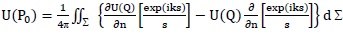
is incident on the diffracting aperture. According to Fresnel-Kirchhoff theory, diffracted field at observation point P0 in terms of incident wave field and its first derivatives at an arbitrary closed surface surrounding P0 is
 |
(2) |
Where ∂/∂n denotes differentiation along the outward normal, Q is a point situated in the diffracting aperture Σ and exp(iks/s) is Green’s free space function, r is distance between source of light and a point Q on diffracting aperture and s is distance between aperture point Q and observation point P 0. Maggi and Rubinowicz converted double integrals used in above formulation into a line integral using Stoke’s theorem, giving [19]
 |
(3) |
Where
 |
represents Young’s boundary diffraction wave generated at the edge of the aperture by it's interaction with incident light. Recently a quantitative criterion has been developed for classifying whether diffraction pattern is of Fresnel or Fraunhofer type [24] giving
Fraunhofer rigion γ ≤ 0.8
Fresnel rigion γ > 0.8
Where
 |
(4) |
Using parameters of our experimental setup the slit-width (1X) = 20 micron, wavelength of laser (λ) = 632.8nm, r = 2mm, and s = 30mm value of γ = 0.0019. Thus, we receive Fraunhofer diffraction pattern at the detector's surface.
Using the method of stationary phase and some approximations the expression of boundary diffraction wave becomes [25]
 |
(5) |
Here dl is an infinitesimal element situated on illuminated edge Γ of the diffracting aperture, λ is wavelength of light used and ϕ is polar coordinate. In case of single slit having width lx the diffracted field can be written as sum of two boundary diffraction waves arising from each edge of the slit, giving
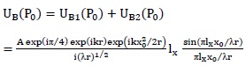 |
(6) |
This equation represents amplitude distribution at observation screen resulting due to single slit diffraction. Here effect of geometrical beam UG, which is small due to small size of slit, has been neglected. Here two boundary diffraction waves staring at each edge of the slit interfere to generate the single slit diffraction pattern having different diffraction orders. Diffracted light propagates along the direction of incident beam with an additional effect of diverging out symmetrically with respect to initial direction of propagation as given by Keller’s geometrical theory of diffraction [26]. If slit width is small than boundary diffraction waves originating from two edges of the slit interfere to generate a single fringe, which forms the beam of light passing through the slit. This is also evident from our earlier discussion in a previous paper where it was demonstrated by using a Lloyd mirror on boundary diffraction wave from a knife-edge [21]. When incident beams at individual slits of the double-slit system enclose large angle (in our case when slits are placed in proximity of focus), light striking at individual slits generates their own single slit diffraction pattern which propagates in different directions (i.e. beams from individual slits are spatially separated) and thus individual slit diffraction pattern can be observed. When angle between beams incident on slits decreases (this can be experimentally realized by moving slits away from focus) separation of light striking on individual slit also decreases and consequently diffracted patterns come closer to each other. This is schematically shown in Fig. (1).
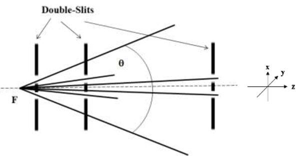 |
Fig. (1). Change in angle θ with change in position of double-slit with respect to laser focal point F. When angle becomes small diffraction patterns from the two slits superimpose to generate Young’s double-slit interference fringes. |
Angle θ between incident beams on slits is related with separation of individual slit diffraction patterns ‘x’ as:
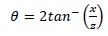 |
(7) |
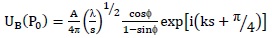
Here z is distance of double-slits (having width lx and separation d) from focal point of the laser. When θ becomes small, separation between diffracted patterns also become correspondingly small and ultimately diffracted light from both the slits superimposes resulting in Young’s double-slit interference fringes with an amplitude distribution:
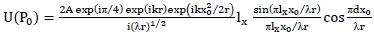 |
(8) |
This equation of field distribution derived using boundary diffraction wave theory is in full agreement with that obtainable with Fourier optics treatment as explained in reference [25].
3. EXPERIMENTAL PROCEDURE
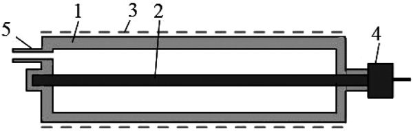
A schematic representation of experimental arrangement is shown in Fig. (2). A He-Ne laser at 632.8nm wavelength is expanded and spatially filtered using the spatial filtering assembly SF (pin hole = 5μm and microscope objective 45 x). Lens L is used to focus the expanding laser beam at point F. Light diverging out from focus F in the direction of beam propagation is used to illuminate a single slit of opening 100μm and a Young’s double-slits (slit width = 20μm and spacing between slits = 250μm), sequentially. Slits were mounted on a linear translation stage with travel length of 25 mm and resolution of 0.01mm. Position of slits and of translation stage is aligned such that at 25mm marking on the translation stage, slits are at focus F. Now slits are translated in the direction of propagation of laser beam such that diverging light falling on individual slits gets diffracted from these and forms individual single slit diffraction patterns. In case of double-slit these diffraction patterns of individual slits are well separated in space on the observation screen. As slits are further translated the angle between light beams, which strike on individual slits, decreases consequently diffraction patterns of individual slits come closer to each other. Finally, individual slit diffraction patterns superimpose on each other, generating the Young’s double-slit interference fringes. Relation between position of double-slit relative to laser focal point F and separation between individual slit diffracted light is shown in Fig. (1). The diffraction patterns are recorded with a CMOS sensor (Lumenera: Lu120MB) placed at a distance 30 mm from the slits. Complete system including slits and sensor is mounted on single platform which infact is installed on the main linear translation stage.
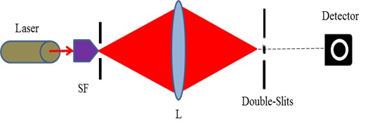 |
Fig. (2). Schematic representation of experimental arrangement. |
4. RESULTS AND DISCUSSION
Experiments are performed to study the step-by-step evolution of single slit diffraction pattern and generation of Young’s double-slit interference fringes due to interaction of light diffracted from the individual slits of the double-slit system. Initially slits are positioned symmetrically with respect to laser focus F and near to it. This position is determined by observing that at this position most of the laser beam is transmitted through the single slit producing uniform illumination on the observation screen and in case of double slits most of the laser beam is blocked by opaque strip between the slits and thereby only weak diffracted light from individual slits passes to observation screen and is well separated in space. Now translation, in steps of 2mm, is given to the slits in the direction of propagation of laser beam and diffraction patterns are recorded, a few of these are shown in Fig. (3a-c) for single slit and in Fig. (4a-c) in case of diffraction from double-slits.
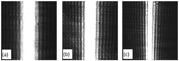 |
Fig. (3). Photographs of single slit diffraction patterns taken step-by-step by moving the slit away from laser focal point. (a) slit at 5 mm from F (b) slit at 11 mm from F and (c) slit at 25 mm from F. |
Fig. (3a) shows a photograph of diffraction pattern generated by interaction of incident beam with the edges of a single slit which is placed at z = 5 mm from the focused image of laser light F. Here since slit is quite close to the focus of laser beam so most of the incident light passes through the slit resulting in the central bright fringe of large width in the slit diffraction pattern and a small amount of light also strikes edges of the slit and thus gets diffracted from these. This interaction of light with slit edges generates the boundary diffraction waves at each edge which further propagate and interfere with boundary diffraction wave generated from the other edge of the slit to generate the interference fringes on either side of the central maxima. These fringes are known as higher diffraction orders of the slit. If distance between slit and the laser focus is increased, only a small portion of incident light passed through the slit and more light gets diffracted from the edges of the slit. This results in decrease in width of central bright fringe and increase of light in higher diffraction orders as is seen in diffraction patterns generated by the slit at distances 11mm and 25mm from the laser focus in Fig. (3b and c) respectively. If number of closely placed slits is increased than interaction between boundary diffraction waves generated from individual edge of the slits take place. For two properly spaced slits this interaction results in Young’s double slit interference fringes as discussed next and if slits are further increased then it generates the effect of a diffraction grating.
Fig. (4a) shows a photograph of diffraction pattern through double-slit placed at z = 5 mm from F. Here individual slit diffraction patterns are well separated in space. As slits are further translated away from the focus, angular separation between incident beams (two points of same diverging beam) on individual slit reduces and hence according to Keller’s geometrical theory of diffraction [24], separation between diffraction patterns of the slits also decreases as shown in Fig. (4b) where distance z is 9 mm. Finally central maxima of diffraction patterns of both the slits superimpose. In this situation diffracted light from individual slits interfere, generating the Young’s double-slit interference fringes as shown in Fig. (4c) corresponding to z = 25 mm. In interference pattern, position of constructive and destructive fringe depends on the phase of interacting photons at that point. If photons are arriving in phase they generate constructive (bright) fringe and if they are out of phase destructive (dark) fringe is produced. At other positions where there is different phase angle between the photons, intensity varies according to their phase relationship. Thus, phase variations between interacting photons result in formation of sinusoidal interference fringe pattern. Here it may be noted that in Fig. (4b) interference fringes are generated only in the area where diffraction patterns from both the slits superimpose while in other areas only diffracted light is available but interference fringes are not observable. In Fig. (4c) where both the diffraction patterns almost superimpose, interference fringes are formed along all the width of the slit diffraction pattern. Here only central maxima of the single slit diffraction pattern is observable. Generation of diffraction pattern of individual slits and formation of interference fringes by superposition of individual slit diffraction patterns clearly demonstrate that two diffracted lights generated from a common incident coherent beam of light could interact with each other. Generation of interference fringes by superposition of boundary diffraction waves originating from individual slits is also in agreement with our earlier investigations on Young’s boundary diffraction wave [22]. As individual slit diffraction pattern is a result of superposition of two boundary diffraction waves emanating from two edges of the slit the double-slit interference fringes are results of superposition of four boundary diffraction waves. But boundary diffraction waves from two edges of a slit combine constructively resulting in a single beam of light and hence Young's double-slit fringes are in fact fringes due to interference of two beams of light.
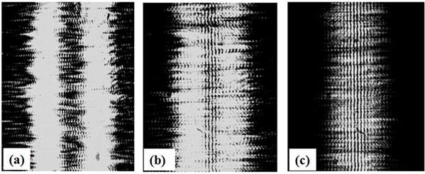 |
Fig. (4). Photographs of diffraction patterns from Young’s double- slits taken step-by-step by moving double-slits away from laser focal point. (a) slits are 5 mm from F and thus diffraction patterns are well separated in space (b) slits at 9 mm from F shows interference fringes only in small central overlapped region and (c) slits at 25 mm from F results in superposition of individual slit diffraction patterns to generate Young’s fringes. |
CONCLUSION
The theory of Young's boundary diffraction wave is used to explain the formation of double-slit interference fringes. According to this theory individual slit gives rise to two boundary diffraction waves corresponding to interaction of incident light with two edges of the slit. Due to small separation between the edges these boundary diffraction waves superimpose to generate the single slit diffraction pattern. Further superposition of light from individual slit generates the well known double-slit interference fringes. An experimental procedure is developed to observe step-by-step the process of evolution of double-slit interference fringes due to superposition of light passing through individual slit. These investigations may be helpful in developing a better understanding about the phenomenon of fringe formation in Young’s double-slit interferometer and hence may provide a clue in solving the paradox of complementarity and uncertainty principles in quantum mechanics.
CONFLICT OF INTEREST
The author confirms that this article content has no conflict of interest.
ACKNOWLEDGEMENTS
Author thanks Mr. DP Chhachhia for interesting discussion and Mr Omendra Singh and Mr Naresh Sharma for technical help during the work. I also thank Prof. B C Chaudhary of NITTTR, Chandigarh for lending his double-slit used in this experiment. This work is financially supported by Council of Scientific & Industrial Research, New Delhi.